Need help with Bolle Mac IIfx recreation board... No Chime, No Reset

pezter22

Well-known member
I have been trying to resurrect my battery bombed Mac IIfx boards (I have two) by transferring everything to Bolle's recreation boards. I love these, but I am having a no boot, no chime on the board(s).

Reset doesn't respond. I've checked and rechecked my soldering. I've got continuity from the pad to the top of the IC's.

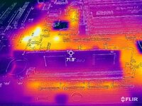
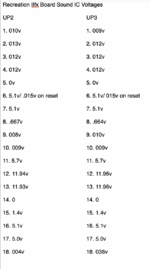
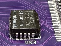
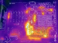
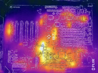
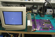
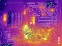
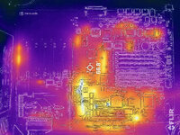
Frustrated I gave up on board one and started putting together board two. My issue today the second board exhibits the exact same issue. Both boards have no chime, no video. There is life on the boards. My FLIR camera shows heat but both boards lack heat with the IC's near the top of the board. Like UC8 which is connected to the Sound IC's is cold. I have a working FX that I can match up everything. The top of the board is active in the working board.

Any help or suggestions would be greatly appreciated. This is such a great way of resurrecting my old Mac IIfx boards.
 

Attachments

  • 1208-mac iifx recreation board 2 flir.jpg
    1208-mac iifx recreation board 2 flir.jpg
    1,006.5 KB · Views: 32
  • 2024-1208-mac iifx recreation bd 1 no chime flir.jpg
    2024-1208-mac iifx recreation bd 1 no chime flir.jpg
    940 KB · Views: 23
  • 2024-1208-mac iifx recreation bd 2 no chime.jpg
    6 MB · Views: 13
  • 2024-1208-mac iifx recreation bd no chime back.jpg
    5.1 MB · Views: 6
  • 2024-1208-mac iifx recreation bd no chime.jpg
    5.2 MB · Views: 6

pezter22

Well-known member
I don't believe the issue is my soldering. I have checked and rechecked all the IC's especially the PLCC chips. All have continuity from pad to top of the pins.

I can only guess that during manufacturing something wasn't connected within the layers. Odds of two boards exhibiting the same issue is pretty high. What is occurring is as if no ROM SIMM installed or the wrong one. I have no chime, no video and no reset. I do get static when reset button is pressed or power button pressed to turn on.

I am missing voltages on the ROM socket on several pins on both recreation boards. I checked voltages with a multimeter and for activity with a oscilloscope. I have a working Mac IIfx board to compare my readings.

What is missing or weak on the recreation board is on Pins 11 and 12
/ROM OE - weak 2.5v (activity on scope) on working IIfx 5.1v (no activity)

Address lines are missing voltages and activity
A4 - 0.12v (activity on scope) on working IIfx 3.4v with activity.

A14 - 0v (no activity on scope) on working IIfx 1.25v with activity.
A15 - 0v (no activity on scope) on working IIfx 2.5v with activity

A43, A44 and A45 I have activity on the ROM socket with low voltages 0.98v. On the working IIfx there are no voltages and no activity.

Birdseed components are on with correct values. No IC's are placed incorrectly or in wrong orientation. I have several ROM SIMMs including a BMOW version. All work on my working board as do the RAM.

It's just weird that both boards have the exact same issue.
 

Attachments

  • 2024-1210-mac iifx recreation rom.jpg
    2024-1210-mac iifx recreation rom.jpg
    2 MB · Views: 13
  • mac iifx recreation bd readings.pdf
    23.9 KB · Views: 2
  • Bolle Mac IIfx ROM schematic.png
    Bolle Mac IIfx ROM schematic.png
    445.2 KB · Views: 12

Bolle

Well-known member
What exactly does "reset doesn't respond" mean to you?
I'm not entirely sure if we already had this in the other thread from a while ago but please check the voltage on both Sony sound chips at pin 6.
Those are the actual reset outputs that will send reset signals to all the other chips on the board. Also check if those change while the reset switch is pressed down.

The reset switch itself is connected to the sense input of both Sony chips. If that input is high (5V) the reset output will become high as well. Pressing the reset switch pulls that input low resulting in the reset outputs being pulled low as well.
R12 (27ohm pullup to VCC), R11 (100ohm in series with the reset switch) and C110 (100nF to debounce the switch) are critical for that circuit to work correctly.
 

pezter22

Well-known member
What exactly does "reset doesn't respond" mean to you?
I'm not entirely sure if we already had this in the other thread from a while ago but please check the voltage on both Sony sound chips at pin 6.
Those are the actual reset outputs that will send reset signals to all the other chips on the board. Also check if those change while the reset switch is pressed down.

The reset switch itself is connected to the sense input of both Sony chips. If that input is high (5V) the reset output will become high as well. Pressing the reset switch pulls that input low resulting in the reset outputs being pulled low as well.
R12 (27ohm pullup to VCC), R11 (100ohm in series with the reset switch) and C110 (100nF to debounce the switch) are critical for that circuit to work correctly.
Thanks for responding.

I really don't think it's an issue with the Sound IC's, but with the ROM. When I say doesn't respond to reset, I have no sound and no response that it's rebooting. To me this is as if there is no ROM or incorrect ROM SIMM installed. I've had this happen when I have worked on my IIFX and forgot to place a ROM SIMM in the socket when I wanted to boot up. I would get no chime, no video.

I do have the proper resistors and capacitors on the board (R12 -27ohms, R11 - 100ohms & C110 - 100nf). There is continuity from R12 to C110.

I am missing or have weak voltages on some pins (address lines) of the ROM socket. I am just don't know where to check for source of voltages. I have checked with a multimeter and a osiliscope First number is Recreation board and second number is Working FX board.
( x indicates activity and - indicates no activity)

Pin 6 0.12 x 3.4 x A4

Pin 11 2.5v x 5.1v - /ROM OE
Pin 12 2.5v x 5.1v - /ROM OE

Pin 37 0v - 1.25v x A14
Pin 38 0v - 2.5v x A15

Any help would be appreciated.
This is a great project of yours.
 

Attachments

  • Screen Shot 2024-12-12 at 7.18.14 PM.png
    Screen Shot 2024-12-12 at 7.18.14 PM.png
    237.6 KB · Views: 4
  • Screen Shot 2024-12-12 at 7.18.35 PM.png
    Screen Shot 2024-12-12 at 7.18.35 PM.png
    245.5 KB · Views: 3
  • Screen Shot 2024-12-12 at 7.23.20 PM.png
    Screen Shot 2024-12-12 at 7.23.20 PM.png
    514.9 KB · Views: 8

Bolle

Well-known member
The CPU is driving the address lines. Measuring switching digital signals with a multimeter isn’t going to tell you anything about if that signal is healthy or not. You have to look at it with a scope to see if there’s activity and to determine if the high level is weak or not. Your multimeter is just going to show you an averaged voltage for a signal that’s switching between 0V for a low level and 5V for a high level. Those measurements you took are not useful for telling if there’s an actual problem with ROM connections.

If you suspect faulty connections to the ROM it might be a better idea to just verify connectivity of each pin instead. All address lines (except the two lowest ones) as well as all data lines are connected right to the CPU. /ROMOE and the two lowest address lines connect to the memory controller.
Check if one of them has no connectivity. If they all check out your problem lies elsewhere. Having the same manufacturing defect on two boards is extremely unlikely.
 

pezter22

Well-known member
I checked the ROM socket to the CPU socket and all the data and address lines had continuity. So this means it is not what I suspected as a ROM issue. I will again go through the IC's and check my soldering (again). I plan on removing one IC at a time and checking, hoping for a death chime at least.

Thanks again for the input.
 

Attachments

  • mac iifx recreation ROM-CPU readings.png
    mac iifx recreation ROM-CPU readings.png
    8.1 MB · Views: 18

pezter22

Well-known member
I'm just guessing it's just the small PLCC chips not properly soldered in place. They look it, but it's tough to tell with the pads underneath the IC. Yesterday I touched up UN9 and when I pressed the power button I at least got a louder static sound from the speaker. So some progress.
 

Attachments

  • IMG_0264 copy.jpg
    IMG_0264 copy.jpg
    1.7 MB · Views: 14

pezter22

Well-known member
These two boards are still not booting. No chime, no video. I have added solder to each PLCC IC (More than what I usually place) just to ensure I have a connection to the board. The pins on all the remaining chips like the Memory Controller, SCSI, NuBus etc... all have continuity from pin to pad. I have no bridges.

Yet both boards continue to have the same issue. Even the FLIR images appear similar. The IC's at the top just don't seem to wake up. I have voltages and there is activity when connected to my oscilloscope. I have continuity between the ROM socket and the CPU. I have proper voltages at the sound IC's.

I just don't know what to look for beyond what I have done. Both boards simply cannot have the same issue. Both boards produced death chimes before being taken apart.

Where else can I check beyond having new boards produced?

Did I miss something when I ordered the boards? Was there something I needed to check during my order process. I just uploaded the gerbers and selected a color. My only choice was, I did not choose to have the bird seed placed on the back of the board.

I just think something is missing. My soldering is usually right on. I am not new to repair. I do board level repairs on newer MacBooks Pros, iPads, iPhones. I have recapped SE analog boards and power supplies. TV's, Stereo receivers, etc... These two boards have me stumped.
 

Attachments

  • 2024-1234-mac iifx recreation board 1.jpg
    2024-1234-mac iifx recreation board 1.jpg
    885.3 KB · Views: 9
  • 2024-1234-mac iifx recreation board 2.jpg
    2024-1234-mac iifx recreation board 2.jpg
    946.5 KB · Views: 6
  • IMG_0310 copy.jpg
    IMG_0310 copy.jpg
    1.5 MB · Views: 8

pezter22

Well-known member
This is such a great project, but at this time I simply cannot recommend it for novice users like myself. I'm a photojournalist/editor, not a engineer. There just isn't much help for this board. I have tried here and on Facebook groups searching for answers why these boards will not produce even a death chime. The boards did produce a death chime prior to being taken apart. I realize it is a big board with lots of components. I just don't know where to look and what component wakes up the board. I am used to working with schematics, but what makes repair far easier is a boardview to follow how and where components are tied together.

I have gone through all my solder joints and there is continuity from pin to pad, even the small PLCC chips with even smaller pads have solder on them. Both boards simply cannot have the exact same issue.

I have two working Mac IIfx and two working extra fx boards, so I can match the components for placement and correct position. I have voltages (multimeter) and activity (oscilloscope). I have continuity from the ROM socket to the CPU. I have proper voltages at the Sound IC's and pressing the reset button drops the voltage on the Sound IC.

I am giving these two boards a rest. I just wanted to resurrect my two battery bombed boards.

Again, this is a great project, but maybe it's just out of my league at this time.
 

zigzagjoe

Well-known member
A Mac IIfx is a rare and very complicated machine, to assemble a new board from scratch means you've got even more possible failure modes than fixing an old board. Unfortunately I think you've summed it up well: This is not a project for novices, you must be willing and able to dig very deep when troubleshooting a freshly built board.

All it takes is one scratch cutting a trace, a missing/incorrect passive part, a damaged part during removal, an unsoldered pad, etc, and you'll get what you described. There's not really general advice practical here beyond verify every single connection, make sure you don't have any dead or (if new) incorrectly programmed parts, make sure any new parts are functional equivalents, and so on.

If the "simple" troubleshooting steps fail, you have to be prepared to probe activity to try to understand where/why it might be getting hung up. As you have working boards, probing them and comparing activity on your bad board as you were doing is a good path forward. But, as Bolle pointed out, you must use a LA or scope (not a meter) as there's no point in comparing voltages. These are high speed signals so a scope/analyzer with sufficient bandwidth/speed is required. Trigger your measurement on /RESET going high; I'd suggest checking if any bus cycles occur (probe /AS, /DS, /DSACK) as a starting point.
 
Top