• Updated 2023-07-12: Hello, Guest! Welcome back, and be sure to check out this follow-up post about our outage a week or so ago.

Macintosh SE SuperDrive Restoration

PotatoFi

Well-known member
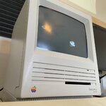
A good friend of mine mentioned that he had a Macintosh SE SuperDrive that didn't work, so I offered to restore it for him. He lives about six hours away from me, so last fall, a mutual friend brought it up to Boise and handed it off to me.

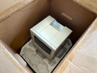
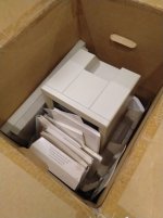
Wow, an original box! I've never seen one before, so this was a bit of a treat to unpack.
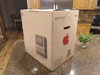
IMG_20190811_220735.jpg

1 MB RAM, 1.4 M DRIVE. Oooooh, that means that this is an FDHD, like mine!
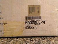
IMG_20190811_220743.jpg

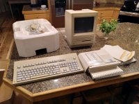
Inside, I found a mouse, a Apple Keyboard II (not my favorite, but seems to be regarded as the "best" keyboard for these), and a whole bunch of manuals, and some software. Very cool.
IMG_20190811_220929.jpg

IMG_20190811_221113.jpg

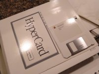
I was pretty thrilled to find this pristine copy of HyperCard in there, along with a lot of other manuals.
IMG_20190811_221117.jpg

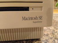
The first thing I noticed is that this one is badged as a "SuperDrive". I think I'd heard of these, but have never seen one. As far as I know, it is identical to my FDHD. I gotta admit that I prefer the "SuperDrive" name to "FDHD", so I'm a tiny bit jealous of my friend's Mac. Do you think he'd notice if I swapped enclosures? Hrm...
IMG_20190811_221034.jpg

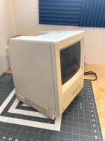
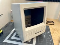
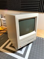
Overall condition on this one is absolutely fantastic. It hardly has a scratch, and there's no visible burn-in on the CRT. This has to be the cleanest, best-looking compact Macintosh I've ever seen. Time has turned it a bit yellow, but it's nothing that some retrobrite can't fix.

The very first thing I always do when I get anywhere near a classic Mac is to check the PRAM battery. Unfortunately, I experienced my very first red Maxell bomb on this one.
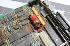
IMG_1058.jpg

The battery must have really "popped" when it went off, as it got the metal chassis as well.
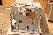
IMG_1062.jpg

The mess was very dry and powdery, which makes me think that it happened long ago. First, I removed what was left of the battery.
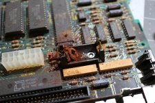
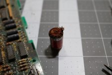
IMG_1059.jpg

IMG_1060.jpg

After removing everything:

IMG_1061.jpg

Next, I gave it a rinse in the sink under tap water. I know this part really freaks people out... but I've never heard of it actually hurting anything. I do it all of the time.
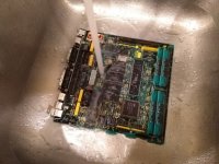
IMG_20190811_223446.jpg

Then, I followed up with some baking soda to try to neutralize whatever acid might be left.
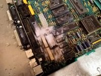
IMG_20190811_223701.jpg

I finished up with another wash under tap water.
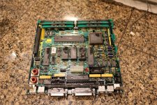
IMG_1064.jpg

I was pretty shocked at how well things cleaned up. This Mac might actually be recoverable!
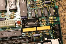
IMG_1065.jpg

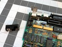
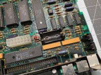
At this point, life got super busy, so with the board "stabilized", I put it all out in the garage and didn't touch it for months. That was on August 11th, 2019. It's now April 12th, 2020, and since we're all stuck at home, I have some time for projects again. Last night, I pulled it out do try to desolder the old, broken battery holder. Looking at these photos, I'm realizing that this doesn't look like the stock Apple battery holders that I see on SE/30's and pizza box Macs. It looks like the modern replacements that I use on SE's that don't have battery holders! Interesting.

Either way, it needs to come off.
IMG_0511.jpg

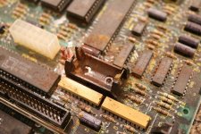
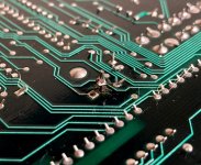
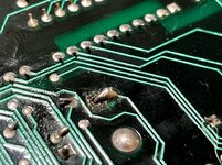
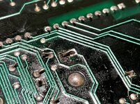
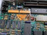
After a lot of messing around, I finally got the battery holder removed. I couldn't really get solder to flow, so I think I kinda more broke it off the board than anything. Underneath, I found this awful orange stuff, which is very hard and glue-like.
IMG_0512.jpg

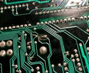
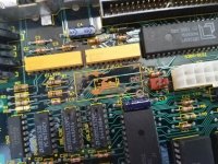
I decided to try to clean this stuff up. I soaked it in vinegar for several hours, and scrubbed it with a toothbrush. That didn't seem to do much, so I switched to a small plastic toothpick and worked away at that for awhile. This is about as good as I could get.

Surprisingly, it didn't seem to eat through the soldermask! There's one wide trace that is missing soldermask, but the trace itself seems okay. I might have ripped the soldermask off while cleaning, but I'm not sure. In retrospect, I'm starting to think that this is an adhesive - not anything to do with the battery. I'd like to hear your thoughts, if you have any.
IMG_20200412_160617.jpg

Since all of the traces look okay, I decided to try powering it on. I dug the SE SuperDrive back out of the garage.

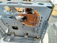
Yikes, I'd forgotten about the extent of the damage. I'll have to deal with this somehow. Maybe a vinegar soak, sand, and... paint? Ready to hear your ideas, let me know how you think I should handle this.
IMG_20200412_160740.jpg

Okay, board is now installed. I plugged in the floppy drive, but not the hard drive. I was pretty anxious to see what would happen.
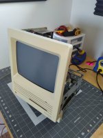
IMG_20200412_160955.jpg

I was pretty shocked that it powered right on, and showed a blinking "?" floppy icon! 
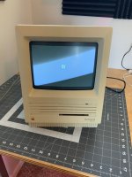
IMG_0518.jpg

But will it boot when I insert a floppy? The drive really labored to accept the floppy disk - a sure sign that it needs to be cleaned and lubricated, which I always count on when restoring these old Macs...
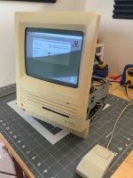
IMG_0519.jpg

Look at that, it boots! And at least one of the ADB ports works just fine. It looks like this restoration is going to be pretty straightforward.

I'm completely out of hydrogen peroxide to retrobrite it, which I think it needs. I can't go to Sally Beauty because of the pandemic, so I was able to order 8 x 32 oz bottles from Sally Beauty for $40, including shipping. We'll see how long it takes to get here - I think I'll wait until it arrives to tear this thing down. I have three Macs to retrobrite so I'll look forward to getting it. When I do, here's what I plan to do:

  • Clean everything
  • Retrobrite the computer and mouse
  • Recap the analog board, depending on what caps I have on-hand (although they all look just fine)
  • Clean and lubricate the floppy drive
  • Fix or stop rust on the chassis
  • Solder in replacement battery holder, but I don't think I'll send it back with a battery installed
 
Last edited by a moderator:

davidg5678

Well-known member
I'm completely out of hydrogen peroxide to retrobrite it, which I think it needs. I can't go to Sally Beauty because of the pandemic, so I was able to order 8 x 32 oz bottles from Sally Beauty for $40, including shipping.
I recently found this product on Amazon which I think is meant to treat dirty pool water. It also happens to contain a gallon of 7% hydrogen peroxide for all of $10, and I have used it to several retrobrite computers without a problem.

I would also be interested in tips about how to deal with the rust. 
When I restored my Macintosh Classic with a battery leak, I had a similar rust problem on my computer chassis. To repair it, I sanded down all of the rust with steel wool and sandpaper, and then I used hammered finish grey Rustoleum paint to deal with the rust. I think I actually prefer the look of the chassis with paint on it compared to how it came stock!

 
Last edited by a moderator:
PotatoFi

Well-known member
I recently found this product on Amazon which I think is meant to treat dirty pool water. It also happens to contain a gallon of 7% hydrogen peroxide for all of $10, and I have used it to several retrobrite computers without a problem.

When I restored my Macintosh Classic with a battery leak, I had a similar rust problem on my computer chassis. To repair it, I sanded down all of the rust with steel wool and sandpaper, and then I used hammered finish grey Rustoleum paint to deal with the rust. I think I actually prefer the look of the chassis with paint on it compared to how it came stock!
Dang, that would be about 1/2 the price, and it would get here a lot faster. I'll look into cancelling my order with Sally Beauty. I was able to get 40 proof, which I think means 20 percent (I don't understand how the proof system works).

As for the hammered finish... I think that would look great. I might only paint that one spot though to try to keep as much of it original as possible. We'll see, still thinking about it.


krishnadraws

Well-known member
Loved the write-up! Glad the SE is up and running again!

I had a similar exploded battery situation on a derelict Mac SE/30. Its chassis had a lot of rust from the Maxell explosion, with some collateral damage on the floppy drive cage.

I recommend dunking the chassis in a vat of apple cider vinegar. Keep it overnight and check in the morning. I've chronicled my experience with this process on this thread.


PotatoFi

Well-known member
Finally back for another update on this Mac! Lots of progress to report.

This week, I have a bin of hydrogen peroxide going for another Macintosh SE restoration that I'm doing, so I decided to knock retrobrite on this one out at the same time. Hydrogen peroxide in the quantities I need is a bit expensive ($40 or so), so I reuse it when I can (but it does seem to lose it's effectiveness after about a week).

IMG_0430.jpg

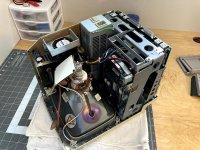
First, I popped off the back, and discharged the CRT per standard procedure. As usual, I didn't hear a "click" or anything. The first few times I did this, I was absolutely terrified, but over time I've become totally unafraid of working around CRT's. I simply always follow the discharge procedure, but I do think that the bleeder resistor that these SE's supposedly have must help.

IMG_0431.jpg

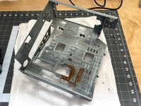
First, I removed the logic board. You can see the rusty spot where the battery exploded and projected acid or whatever it is up at the chassis.

IMG_0432.jpg

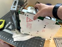
Next, the analog board needed to come out. After removing the four screws and grounding wire, I lifted it out the front. I do dislike how you have to flex the chassis a bit to make room to remove it on the SE. The Classic and Classic II have a much more elegant design, in my opinion.

IMG_0433.jpg

With the analog board removed, I next removed the CRT. Again, I used to be terrified of handling these, but I think the only dangerous stuff happens under the anode cap, which has been discharged.

IMG_0434.jpg

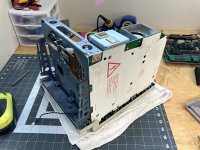
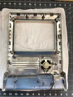
Next I removed all of the Torx screws holding in the chassis, and lifted it away. We'll revisit it in a bit.

IMG_0435.jpg 

Now we just need to deal with the speaker.

IMG_0436.jpg

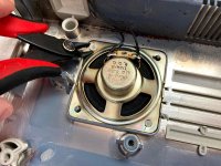
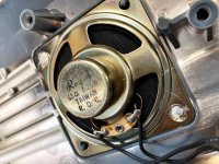
To remove the speaker, I use a pair of Hakko flush cutters to snip away the melted plastic posts. I'll use hot glue to hold this speaker back in place later. I do like to leave enough plastic that the speaker "snaps" back in, if I can.

IMG_0437.jpg

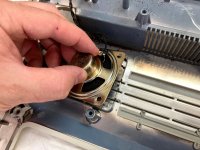
With the plastic snipped away, the speaker lifts out.

IMG_0438.jpg

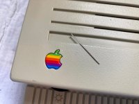
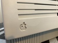
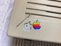
In preparation for retrobrite, the pristine Apple badge needs to come out. The heat and direct sunlight can bleach the red and white colors, which we don't want. I've been watching for spare Apple badges for awhile, but haven't found any. I worry that people just throw away cracked cases and enclosures without thinking to save the badges.

IMG_0439.jpg

To poke out the badge, I use a needle with the end snipped off. Using a needle by itself can be too sharp, and can puncture the badge or leave a tiny "reverse dent" in it. Usually you can poke badges out with paperclips, but not on the SE; the access hole is too small.

IMG_0440.jpg

With that, the front is ready for cleaning and retrobrite. Next, let's remove the floppy and hard disk from the chassis. I always use my impact driver on these to make sure I don't mess up the Phillips heads.

IMG_0442.jpg

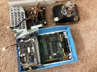
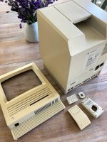
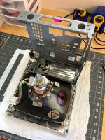
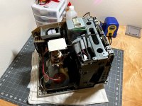
The machine is all taken apart! I've gotten to a point where I can do this in about 5 or 10 minutes. These Macs are very simple once you get to know them.

IMG_0443.jpg

IMG_0435.jpg


PotatoFi

Well-known member
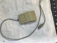
With a nice hot day and full sun available, it was time for some retrobrite! I won't get to the keyboard right now, but I can definitely get the Mac SE and mouse done. Here's the mouse before:

IMG_0445.jpg

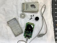
They come apart super easily.

IMG_0446.jpg

Next, I did my usual cleaning. I always start with dawn dishwasher detergent and a toothbrush. After that, I scrub away imperfections with a wet paper towel and baking soda. The baking soda does remove a bit of texture if you scrub too hard, so I am careful to take it easy. The reality is that this Mac is in such great shape that it didn't need much detailing.

IMG_0457.jpg

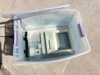
Into the peroxide it goes! I used five 32 ounce bottles of 40-proof hydrogen peroxide and water in this container. Note the fish tank heater: I can preheat the water overnight to ready it for the morning sun. It will bring the water up to about 90°F / 32°C. 

Also note the trick I use to hold down the small "floaty parts" I've recently discovered that trapping them under a glass dish works great!

IMG_0463.jpg

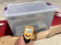
By mid-morning, things had gotten nice and warm! 110°F / 43°C seems like the threshold where things get super effective.

IMG_0476.jpg

It was a nice, hot day, so after only a few hours, the parts were done. I always pull them out of the peroxide, hose them down with fresh water, and towel dry them before taking them inside. My neighbors probably think I am super weird.

IMG_0484.jpg

Curiously, despite my using the "full submersion" method, there is a light spot on the front of the case. I really don't know why this would happen. Possibly light was focused here? Seems likely, but I find that I don't really have to rotate parts to make sure the sun hits all sides... I'm starting to think that most of the reaction is due to heat.

Fortunately, the defect is hardly noticable.

IMG_0485.jpg


PotatoFi

Well-known member
While the parts were in the hydrogen peroxide getting the retrobrite treatment, I took the chassis over to my brother's house to sandblast the rusty part. My brother makes AR-15 lower receivers, so he has lots of great tools, such as a gigantic Haas mill. His shop is pretty great, he can make pretty much anything!

IMG_0444.jpg

The sandblasting cabinet worked great, but it is hard to see into.

IMG_0464.jpg

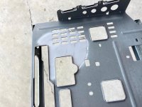
Here's what it looked like when I was done. He recommended not touching it or doing anything to clean it, "Just take it home, hit it with compressed air, and apply primer." He also handed me a can of automotive high-temperature primer. Sweet, free primer!

IMG_0468.jpg

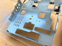
Here's what it looked after some primer. Not quite a perfect color match, but close enough.

IMG_0470.jpg


PotatoFi

Well-known member
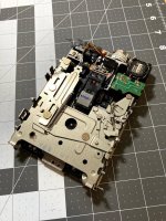
Next, it was time to clean and lubricate the floppy drive. Before this, it worked fine, but the eject motor seemed to really struggle.

IMG_0494.jpg

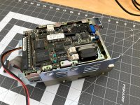
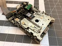
I got the drive out of the bracket, and found that it was dusty, but pretty clean compared to many of the drives I've seen.

IMG_0495.jpg

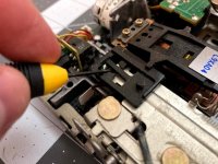
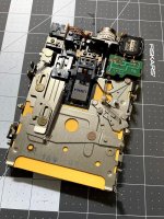
The first step is to remove the plastic bracket that lifts the upper read/write head out of the way when the disk is ejected. To remove it, you gently lift the small tab in the center and slide it towards to back of the drive.

IMG_0496.jpg

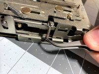
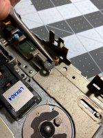
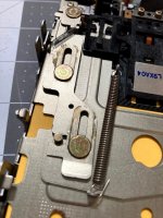
Next, I use tweezers to release the two springs on the sides. There's one on the right, and one on the left, and they are released from the bottom of the drive.

IMG_0497.jpg

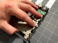
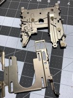
Next, we need to release the upper part of the drive so we can lift it away. It's a bit hard to show in the photos, but you can see where my fingers are sitting on two mechanism that pivot/slide back and forth. Basically, you just slide them away from the each, which will disengage parts of the drive causing it to separate. You'll know when you've done it right, the drive snaps down very suddenly. It's not scary or anything, you'll just know when it worked.

IMG_0498.jpg

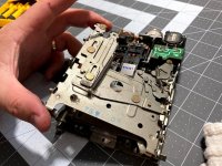
Once the top has snapped down, you can lift the top out from the left side. You might have the slide the lower tray forward and backwards a bit to clear everything, but you can work it out pretty easily.

IMG_0499.jpg

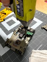
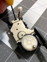
With the upper tray removed, it's time to remove the eject motor and gears. I use my impact driver on these to make sure I don't round out the Phillips heads, which I have done. And it sucked.

IMG_0500.jpg

To remove the lower tray, there are four little snap rings to remove. I use a pair of needle nose pliers to pop them off.

IMG_0502.jpg

And with that, the drive is disassembled and ready for cleaning! Let's tackle the eject gearbox first. Releasing the cover is pretty easy, just press a small screwdriver into the clip towards the back. Be gentle here... I haven't broken one of these yet but I would not be surprised if this plastic was super brittle.

IMG_0505.jpg

I didn't get a picture, but the gears looked great. I added a couple of drops of DuPont Silicon Teflon lubricant.

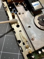
Next, I cleaned up the upper and lower carriage mechanisms on the drive. I just scrubbed them down with a toothbrush and Dawn dishwasher detergent, and then blew the moisture out with the air compressor.

IMG_0506.jpg

The drive itself got hit with the air compressor, and then I used cotton swabs and alcohol to clean up any remaining grease.

IMG_0507.jpg

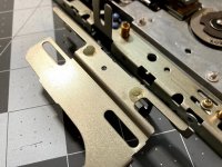
Next, I used the little tube of lubricant that came with my Prusa i3 MK3S printer to lubricate the sliding parts. It's a bit thinner than lithium grease.

IMG_0508.jpg

After lubricating, I installed the bottom carriage, and snapped the rings back in by just pressing them on with my thumb. Then I set the upper carriage back in place, used tweezers to reconnect the springs, and actuated the things to pop it back into place. As I write this, I realize how difficult the process is to describe, but once you get it, it is very simple.

IMG_0510.jpg

Finally, I reinstalled the small plastic clip that lifts the upper read/write head, and tested a disk! This is a dead disk that I use as a coaster on my desk.

IMG_0511.jpg

The disk seemed to eject a little half-heartedly. Whoops, forgot to lubricate some of the parts on the top carriage. No problem, not too late.

IMG_0512.jpg

Disks fly out of the drive now! To finish up, I reinstalled it in the hard drive caddy.

IMG_0513.jpg


PotatoFi

Well-known member
This restoration is getting SUPER close to being done. At this point in time, I had three compact Macs torn apart at once, so I decided to put a few things back together to reduce the chaos a bit.

First, I hot glued the speaker back into the front of the case. I just do a dab of hot blue where the plastic posts were. The trick is to push the glue down into the holes a bit to hold it into place.

IMG_0487.jpg

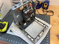
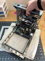
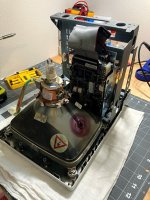
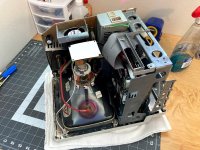
CRT reinstalled, chassis installed.

IMG_0488.jpg

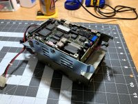
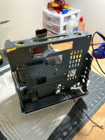
Floppy/hard drive bracket installed. No more rusty chassis!

IMG_0514.jpg

IMG_0515.jpg

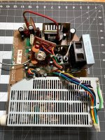
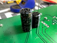
Next, it was time to do a light recap on the analog board. To be honest, I only see one cap that is even remotely suspect... but I wanted to get this done now while I have it apart. I've created a cart on DigiKey with all of the caps needed for the analog board, sans the power supply (which I have yet to have trouble with on an SE).

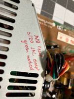
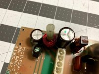
Most likely due to the current pandemic, a couple of the caps weren't available, and I couldn't find a suitable replacement. I marked all of the caps with a green Sharpie before desoldering anything, so it be clear for the next person (or me) if and when the un-replaced caps fail.

Usually, this is where I post a shopping cart link, so you don't have to dig for capacitors. I'll update this post with a link soon.

IMG_0521.jpg

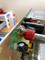
I did the caps in small groups at a time to avoid desoldering a cap that I couldn't replace. Whenever I spec caps, I always find something that is the same capacitance, and the same leg spacing so it fits nicely. I will also substitute a higher-voltage cap in many cases.

Here's a random photo of a capacitor getting soldered in. Sometimes, I'll solder one leg, apply pressure from the top of the cap, and reheat the solder to seat the cap firmly against the board.

IMG_0522.jpg

This one was a huge pain due to the hot glue. I was worried that I'd broken the component next door but it ended up being fine.

IMG_0524.jpg

I wrote a quick note on the board explaining the green marks.

IMG_0525.jpg

Here's one of the caps I couldn't replace:

IMG_0526.jpg

All done!

IMG_0527.jpgAll 

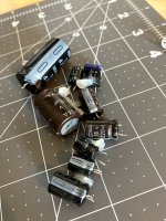
Pile of old caps. I was a bit tempted to save these but... nah.

IMG_0528.jpg


PotatoFi

Well-known member
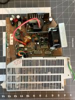
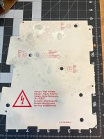
Before I put everything back together, I cleaned the Analog Board shield. I forgot to get a "clean" photo of it, sorry about that! But rest assured that it is very clean now.

IMG_0538.jpg

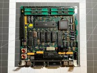
All that's left is the Logic Board.

IMG_0540.jpg

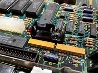
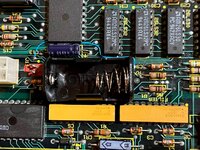
Since the battery blew up, the original battery holder was absolutely toast. Luckily, it didn't seem to do much damage around it! The orange stuff that you see I believe is some kind of adhesive, not fallout from the battery. But the through-holes for the battery were a total mess.

IMG_0545.jpg

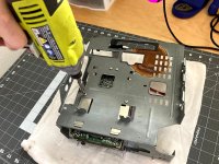
To burn through all of the corrosion, I used a bunch of liquid flux, a ton of heat (750°F on the iron), and repetition to clean out the holes. I would flux, heat, solder, desolder wick. I did that 3 or 4 times when finally, the corrosion and rust was all burned out, and I could see through the hole.

But then, disaster! When I pushed the battery holder through, soldered it, and then reheated the joint to full seat the battery holder, the pad popped right off! I had to abuse it pretty hard to get solder to flow, so while I was disappointed, I wasn't surprised.

IMG_0549.jpg

Fortunately, the adjacent terminal is electrically connected. So I just bent the leg over and soldered it down to that. Not pretty, but it will work.

IMG_0550.jpg

Board is done! I'm not going to install a PRAM battery, because it isn't needed to boot this machine, and due to the pandemic, I'm not sure when I can deliver this machine back to my friend, and I do not want to ship it. Sadly, it will most likely sit in my garage for a few months.

IMG_0551.jpg

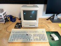
Reassembled!

IMG_0552.jpg

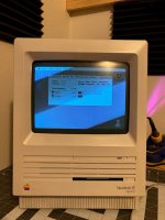
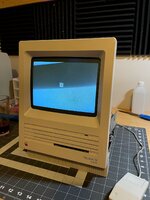
Does it work? Here's what it did with a floppy disk boot!

IMG_0554.jpg

But there are three issues that I need to sort out:

1. The floppy drive squeaks! It's absolutely the drive motor or mechanism. It changes speed constantly. Very weird. It didn't do this before. The drive does read and write, though.

2. It won't boot from the hard drive, which is no surprise. But what is surprising is the sound! Check it out!

3. There's no beep when the system is first powered on. Perhaps the sound is damaged on the logic board?

I could use a bit of help on these so if you have ideas, please let me know. Especially about the sound.


davidg5678

Well-known member
This one was a huge pain due to the hot glue. I was worried that I'd broken the component next door but it ended up being fine. 
I have found that a drop of isopropyl alcohol removes hot glue incredibly easily. (The glue even stays in one piece!) When I am desoldering these analog board capacitors, I remove the glue with alcohol first, and they pop right out with minimal effort.


PotatoFi

Well-known member
I have found that a drop of isopropyl alcohol removes hot glue incredibly easily. (The glue even stays in one piece!) When I am desoldering these analog board capacitors, I remove the glue with alcohol first, and they pop right out with minimal effort.
Fantastic! I have two more SE analog boards to recap in the next couple of days. Thank you very much for the tip!


TAinKC

Member
2. It won't boot from the hard drive, which is no surprise. But what is surprising is the sound! Check it out!
That's a MiniScribe stepper motor hard drive - they tend to get a bad rap but make a set of sounds like none other.

If you can't get HD SC Setup to recognize it, try Lido instead - I had a couple of those drives that I'd all but given up on. Lido worked when everything else failed.


Franklinstein

Well-known member
Those MiniScribe 8425 drives are usually pretty reliable, though they're slow. They tend to make a lot of drama out of the smallest disk access, which is amusing, and they occasionally run a thermal recal routine which results in some clunks and peeps from the drive even when it's idle.

There's one problem with them, though (common to most stepper motor drives): they don't auto-park the heads, so when the disk spins down, the heads land on whatever spot they're currently over. Not good for your data, especially if the drive receives shock in this state. It's best to use a driver utility such as Silverlining and enable the head parking feature, which automatically moves the heads to the innermost track before a restart or shutdown. This causes this particular model of drive to make an unsettling BRRRRRT noise at the next spin-up when the stepper motor hits its innermost limit during the startup routine, but that doesn't seem to cause any problems and it occasionally happens on its own anyway if the heads land on some of the inner tracks between power cycles.

Occasionally the drives will suffer from corrupted EPROMs which will render them useless even though the media is still ok. They can sometimes be resurrected if you find a copy of the same version ROM and re-burn the chip.


LaPorta

Well-known member
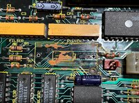
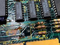
When my SE battery exploded, many of the traces that were sound-related around the speaker terminal were damaged. I'd check them with the multimeter and make sure there was no damage.

As for the battery, after looking at a few boards, I realized that they put in the two different spaced battery terminal through holes for different sized components. you can use any combination of two to make a connection (as you did).

Lastly, that orange crud did come off my board with some real work.It was in exactly the same place. It was hiding some rotten sound traces that run directly under the battery holder. I would focus my efforts here to find your sound issue. You can see in my photos:


Last edited by a moderator:
PotatoFi

Well-known member
Note: This post was lost in the Summer 2021 68kmla forum crash. I was able to find it on the Wayback Machine, copy the text over, and find the matching photos. The original post is from May 17th, 2021.
After nearly a year, I've finally got motivation to get this project done: a deadline. This machine's ride was set to pass through town today, so last night, I decided to stay up late and get this machine across the finish line.
IMG_2412.jpg

The first thing that I needed to address was the sound issue. I decided to start by investigating the traces under the battery, which means the new battery holder that I installed needs to be removed.

IMG_2413.jpg

I used the iron and a solder sucker to desolder the holder. For Christmas, I received a genuine SOLDAPULLT. If you're using a cheap desoldering pump, I strongly recommend getting a real SOLDAPULLT. Here's an Amazon Affiliate link if you want to grab one.

IMG_2414.jpg

IMG_2415.jpg

With the battery holder removed, I scraped a bit of solder mask off of some of the vias, and started testing for continuity.

IMG_2416.jpg

One thing that I needed for this was a schematic, but I haven't been able to locate a good one for the SE. The only example out there that I could find is super blurry - basically unreadable. @Kai Robinson's Mac SE reverse engineering was super helpful here - I was able to look at photos of his work, and follow traces around.

Note: I'm not sure whether I showed a photo of Kai's work in the original post or not.

IMG_2417.jpg

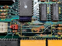
Ultimately, I was able to identify a bad trace, and put a bodge wire in to fix it. Since I don't have an actual schematic, I couldn't figure out what this trace actually does - it seems to run around for awhile (just for fun, I think) before going across a resistor and then to ground.

IMG_2420.jpg

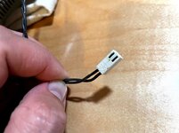
Sadly, that didn't fix the sound issue. But then it occurred to me - I should try out the headphone jack. I plugged in some headphones, and got a bong. Then, I shoved some jumpers into the speaker connector and touched them to a AA battery. There were no crackles from the speaker, so I decided to just cut the cable any bypass the connector. Success! Now, the AA battery generated some crackles, telling me that the connector was probably all rotted out due to the battery. No surprise - I wish I'd checked this first!

IMG_2421.jpg

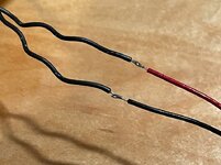
I happened to have a similar connector in my box-of-wires from an old 3D printer build (specifically from my scratch-built Printrbot original, way back in 2011 and 2012), so I soldered it into place.

IMG_2422.jpg

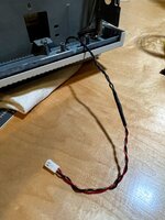
Heatshrink, and done.

IMG_2423.jpg

I tested everything on the bench, and success! Nice, clear audio from the speaker. With everything working, I reinstalled the battery holder from RetroFixes.com.

IMG_2424.jpg
 

PotatoFi

Well-known member
Note: This post was lost in the Summer 2021 68kmla forum crash. I was able to find it on the Wayback Machine, copy the text over, and find the matching photos. The original post is from May 17th, 2021.

At this point, it was pretty late... 11 PM or so. I needed to move pretty quick to get this one and get some sleep. It was at this point that I remembered: The MiniScribe drive doesn't work, and the machine won't boot.

IMG_2425.jpg

Rather than troubleshoot the drive, I decided to assemble and install a BlueSCSI. I ordered four of these from @erichelgeson a few weeks ago - these are fantastic kits to have on hand for situations like this. You know... situations where you're restoring a Mac SE for a friend, and have a deadline, and it's 11 PM. That type of situation, specifically.

If you want to order a BlueSCSI kit, you can find them here.

IMG_2427.jpg

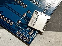
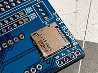
Per the assembly instructions, I started with the MicroSD card slot, which is the only surface-mount part on the BlueSCSI. For SMD parts like this, my method is to:

1. Tin one pad
2. Get the part ready to "slide" into place with some tweezers
3. Heat up the solder on the tinned pad
4. Slide the part into place
5. Remove heat
6. Remove tweezers

Here's one of the pads, tinned:

IMG_2428.jpg

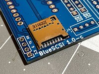
And here's the part after sliding it into place, and removing the heat. What's great is that you can easily reheat the pad if you need to nudge the part around a bit.

IMG_2429.jpg

Next, probably the hardest part of BlueSCSI assembly: the MicroSD card reader pins. I hit them with some no-clean flux, and put a tiny bit of solder on the tip of my iron. Then, I just touch each pin, and the solder flows to the pin and pad. It's easy to add more solder, but it's hard to take solder away - so just work slowly and patiently. This is only the second BlueSCSI I've soldered together, but I find this to be super easy.

IMG_2430.jpg

Next, I double-checked for bridges, and then added a bit of solder to the surrounding pads that are just there for mechanical reasons.

IMG_2431.jpg

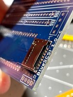
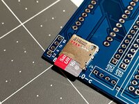
I checked to make sure that the MicroSD card fit - too much solder would have prevented it from working, but it's just fine here.

IMG_2433.jpg

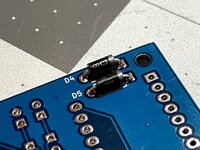
Next, I installed the two diodes on the back of the board.

IMG_2432.jpg

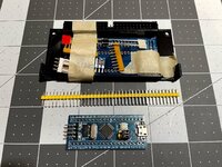
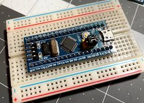
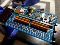
After that, it was time to install the header pins onto the BluePill. For this, I always use a breadboard. Push the headers into the breadboard (long side first), then place the BluePill on top of the headers. Then you can easily solder everything in, and it lines up perfectly.

IMG_2435.jpg

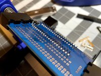
Next, I soldered the BluePill and headers to the BlueSCSI. Note that I don't bother trimming the leads.

IMG_2436.jpg

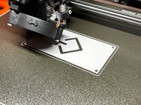
The reason why I don't bother trimming the leads is that I use a printed mount of my own design, which leaves plenty of space for the leads. More on this in a bit, but worth noting that I decided to get one of these printing on my Prusa MK3S. My material of choice here is PETG, and the build surface is Prusa's textured steel sheet.

IMG_2434.jpg

Next, I soldered in the resistor nets. I have a trick for parts like this:

1. Somewhere towards the middle, add a bit of solder to one (and only one) of the through-holes.
2. Gently hold the part against all of the holes. Obviously, it won't go through them, because one of the holes is full of solder.
3. Flip the board over awhile holding the part against the holes.
4. Heat up the solder in that one hole. Suddenly, the resistor net will pop through all of the holes.
5. Remove heat, and now, the part will stay put perfectly while you solder the other holes.

IMG_2437.jpg

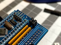
Next, I did the same for the jumper headers.

IMG_2438.jpg

The last two parts were the Molex connector, and the 50-pin shrouded SCSI connector. For the SCSI connector, I use another trick:

1. I load up the tip of my soldering iron with a bunch of solder.
2. I pop the header into position, and flip the board over.
3. While holding the header into place, I touch the iron to a pin on one of the corners. Some of the solder will flow onto the pin and into the hole. It won't be pretty, but it will be just enough to hold the header into place.
4. I solder the opposite corner on the header.
5. At this point, I stop to check and ensure that the header is perfectly flush with the board. If not, I apply gentle pressure to the header (to push it firmly against the board), and head the solder on one of the corners. The header will settle against the board as the solder melts.
6. Solder the rest of the pins.
7. Fix the inevitably bad solder job on the very first pin that you soldered.

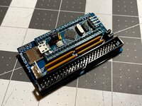
IMG_2439.jpg

That's it, one assembled BlueSCSI! Next, we'll load up an image, install System 6, and cruise to the finish line.
 

PotatoFi

Well-known member
Note: This post was lost in the Summer 2021 68kmla forum crash. I was able to find it on the Wayback Machine, copy the text over, and find the matching photos. The original post is from May 17th, 2021.

To set up the BlueSCSI, I started by formatting my MicroSD card with my modern macOS Big Sur machine. Note: The screenshot is missing, but I think I just did it with the Disk Utility in Big Sur.

Next, to prepare, I grabbed two images:
  1. A blank 1000 Mb image for working storage.
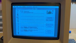
  2. The RaSCSI Bootstrap image, which has some handy utilities, such as LIDO 7.
After placing both images on my MicroSD card, I renamed them:
  • HD00_512 MacSSD.hda
  • HD10_512 Bootstrap.hda
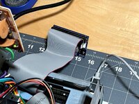
Next, I connected the BlueSCSI to the machine.

IMG_2440.jpg

I booted up the machine, and while the RaSCSI Bootstrap image showed up and worked great, I had difficulty partitioning and formatting my 1000 Mb image. It was after midnight by this point, so things are a bit hazy... but I don't think LIDO 7 or the patched HD SC Utility worked. Ultimately, I think the installer on my System 6.0.8 disks are what did the job, but I don't remember for sure.

IMG_2441.jpg

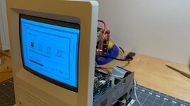
With the partitioning and formatting out of the way, I installed System 6.0.8 from my 800k floppy disk set. I would LOVE to have a set of real, OEM Apple 6.0.8 install disks... but for now, I just use some that I made with my SE/30.

IMG_2446.jpg

By the way, remember the squeaky floppy drive? It squeaked like crazy the whole time - always when the drive was spinning the disk. After awhile, it stopped squeaking and the drive became totally silent. I guess I'm good with that.
 

Attachments

  • IMG_2448.jpg
    IMG_2448.jpg
    436.7 KB · Views: 10

PotatoFi

Well-known member
Note: This post was lost in the Summer 2021 68kmla forum crash. I was able to find it on the Wayback Machine, copy the text over, and find the matching photos. The original post is from May 17th, 2021.

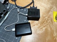
Overnight, I plugged in a LocalTalk cable, and moved a bunch of applications and games over to the machine. I would have just used my handy RaSCSI, but I ran into an issue where the machine would refuse to boot if the RaSCSI was connected. It works fine with my SE/30 and SE FDHD, so I suspect an issue with the external SCSI port. I didn't have time to troubleshoot it, so I fell back to using LocalTalk.

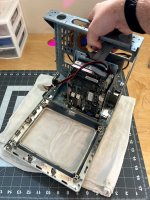
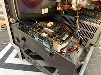
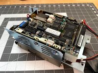
The next morning (and the day that it was to be picked up), I got to work buttoning everything up. Time to swap out this old hard drive.

IMG_2449.jpg

Drive bracket is out.

IMG_2450.jpg

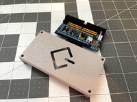
Here's the new 3D-printed bracket, fresh off the printer.

IMG_2451.jpg

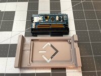
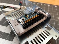
The BlueSCSI's that I bought from Eric include a perfectly good 3D-printed bracket, but since he's basically mass-producing these, the print needs to be highly time-optimized. I decided to do my own design that doesn't need to print as fast. If you want one of these brackets, you can either buy one from me, or print your own for free.

IMG_2452.jpg

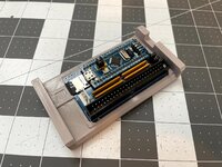
Here's the BlueSCSI, installed in the bracket.

IMG_2453.jpg

Installed in the hard drive bracket, using the original hard drive screws. I try to keep all of the "original" stuff with the machine, including the screws and Molex power cable for the hard drive. That way, it could be put back to "stock" very easily in the future, if someone wanted to.

IMG_2454.jpg

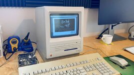
All put back together! One last thing - I need to install After Dark!

IMG_2455.jpg

I think this one turned out pretty good.

IMG_2461.jpg

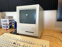
You might have noticed that the keyboard isn't done. I've decided to send the machine home, but hold the keyboard back to get retrobrite done on it. It's just getting warm enough here for retrobrite to be effective.

IMG_2464.jpg

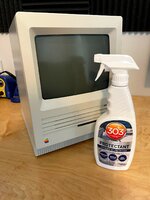
One last thing that I've started doing to all machines I retrobrite: 303 Aerospace Protectant. It's similar to Armor All, but is less greasy, and is specifically designed for UV protection. I apply it generously with a paper towel, and then use a cloth to wipe the excess off. It feels very much like waxing a car.

IMG_2465.jpg

So far, I've retrobrited a bunch of machines - the oldest being my own Macintosh SE FDHD, which I did back in 2018. It has yellowed quite a bit since then - it's still a LOT better than it was before retrobrite, but it certainly has yellowed. As for storage: it lives in a Macintosh carry-case in the closet, completely away from light and heat.

About 6 months later, I restored a Classic II and gave it the 303 Aerospace Protectant treatment. Ever since then, it's sat out in the open on a shelf in my office. There's no direct sunlight, but it does get secondary sun regularly. It still looks minty white, which leads me to believe that the Aerospace Protectant does something to protect and stabilize the plastic. Here's an Amazon Affiliate link if you want to pick some up online, but you might be able to find it locally, too (I think the secret is getting out).

IMG_2539.jpg

And this is where the story comes to an end. Back into the original box it goes. It was picked up a couple of hours later.

IMG_2466.jpg

Thanks for reading my restoration thread! I hope you enjoyed following along.
 
Last edited:
Top