• Updated 2023-07-12: Hello, Guest! Welcome back, and be sure to check out this follow-up post about our outage a week or so ago.

Macintosh Plus Internal Hard Drive *Mod*

Cosmo

Well-known member
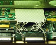
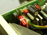
Hope this helps. Just slided the board to get slighly better shot out of it. It's tight packed with power connector, hdd power connector and the opened up scsi cable with the leads soldered on the chip. Would be risky to pull the whole board out. If you want higher resolution picture, PM me.is mi

Edit: Aww.. might need to take another one, difficult to see where the stripes of scsi wiring goes! :disapprove:
MacPlusSCSI.jpg


Cosmo

Well-known member
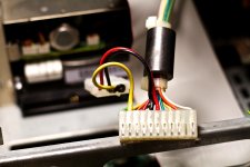
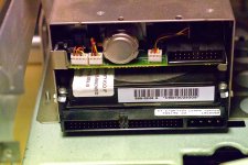
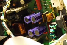
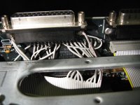
Ok, finally.. Here are better pictures. That is quite a tricky to open up, those cut-wires are bit in a tight fit from the board to connector. Not much space around. Hope these provide any help. If you need original 18Mpix images, PM me with email address.

SCSI_wiring.jpg

Molex_wiring.jpg

SCSI_drive_connector.jpg


uniserver

Well-known member
Thank you for those awesome pictures sir!

Hey so it looks like the only A/B mod is a Different / Larger Capacitor? @ C1


uniserver

Well-known member
I'm real close to giving this another try!

After doing all these Macintosh Portable HD cables… I now know, and understand the grounding situation a little better !!! :)

Also i am still going to use a external PSU to power the hard drive,

I have 2 12v pie fans I am going to mount, those will also be powered from the external psu.


CC_333

Well-known member
You could tap into the A/B's AC in port (just past the switch) and run everything off one cord (and have it switch on and off with the machine as a bonus).

Also, an uninformed person would never know it's been upgraded, because there wouldn't be any outward signs of it.

c


uniserver

Well-known member
Yes, and you didnt read my first post of this thread.

10 Oct 2012, 13:15

i've already done this hack to my Macintosh Classic, because i am to lazy to replace the analogue board,the analogue board was not making enough power to spin up the hd, so i added my own,
 

Nathanplus

Well-known member
K.I.S.S. live by it!

Fixed the boo-boo & didn't stop . . . |)

View attachment 17254

I think it's laid out, but I'll need to review it when I'm relatively conscious again . . .

I need to "cut the corner" on lines DB1-DB7 to keep those traces as close to the length of the DB0 trace as possible.

No biggie, but I'd appreciate some feedback on accuracy of the pinouts and trace routing aforehand, gang. TIA.

I've got six jumper wires (yellow pads) designed in to lengthen the signals bunched up in the center . . . makes it better . . . and easier . . .

. . . and they're ALL hidden underneath the socketed SCSI Controller IC. [:D] ]'>

View attachment 17255

zzzzzzzzzzzzzzzzzzzzzzzzzzz xx(
wait why is RST on the wrong side of NRC 5380


Trash80toHP_Mini

NIGHT STALKER
Booboo probably, I was asking for feedback like this on the layout way back then. In the meantime, someone (Alaska?) developed and was selling a proven design. Dunno how my design stacks up on the kluge scale by comparison, likely much worse as this graphic was a feasibility study in terms of form factor.

 
Top