JC8080
Well-known member
I just finished my build of a Performer accelerator clone for the Mac Plus/SE. Enormous thanks to @Bolle, he reverse-engineered an original accelerator and posted the board file online, along with the GAL files. Thanks to @DrGonzo, his thread on his Performer build inspired to do my own. Link to his thread below.
I started by uploading the board files to JLBPCB. I left all the options at their default setting, except I selected the blue board instead of green. After a new-user $10 discount, including shipping, five boards cost me right about $50.
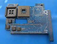
Front

Back

I started by installing the passive components (resistors/capacitors). I selected black tantalum capacitors to match the board color, I didn't like how the yellow ones would look.

Next I moved on to the GALs. I purchased a T48 programmer on Amazon for $72, there are multiple versions/sellers, I selected one that had the correct 20-pin PLCC socket. The GALs were purchased from eBay, $12.99 for 15 GAL16V8D-15LJ chips. As mentioned in DrGonzo's thread, the "A" version will not work, but anything "B" on should work. I programmed the chips and installed them.
Note if you are using this board in a Mac SE you do not need GAL U7, and you DO need to bridge the SJ2 pads. If you use it in a Plus you will need to install U7 and make sure the SJ2 pads are not bridged.
The Xgpro settings I successfully used are not shown in the image below. I used the "GAL16V8D-@SOIC 20", not "GAL16V8D" as shown in the photo. I un-checked encryption, and when I clicked the PROG. button I left both default options checked (FLASH and LOCK-bit).

I don't have a lot of SMD soldering experience, but I am pretty decent at it. That being said, I could not get some of the GAL pins to properly solder to the pads. No amount of solder and flux was doing it. I used a small chisel tip on a good Hakko iron. Finally I bought some ChipQuik solder paste and it worked great. I used my $40 hot air station (from Amazon) to remove all the GALs, and re-installed them with the solder paste. I followed up on each pin with my iron to make sure all the flux/solder mix melted properly.

Next I installed the 68-pin socket to attach to a Plus logic board, and the 96-pin header to fit the SE PDS slot. In DrGonzo's build he used a Euro DIN male connector for the PDS instead of the PIN headers and had problems with the socketed CPU interfering with the case. I went with the pin headers to add a bit of extra clearance. In my machine there are no clearance issues, there is probably 1/16" or 1/8" of space above the CPU. I believe there are two different SE chassis, mine seems to have extra space, I don't know how to identify which is which. In my case I could have used the Euro DIN and been fine. Also worth noting, the CPU does not need to be socketed, it can be soldered directly to the board and this will eliminate any potential clearance issues. I went with the socket since I was buying my CPU off eBay and did not trust that it would work. I don't have the proper equipment to un-solder the CPU, so I played it safe with a socket.
I then moved on to the CPU and FPU sockets. Both were very straightforward through-hold jobs. For the first test I left the FPU out. The photo below with the FPU was taken later.
Completed board, front and back


I switched the machine on, and... Checkerboard screen.
Clearly this was not the desired result. This board is pretty simple, there is not a lot going on, so I hoped the troubleshooting wouldn't be too bad. I started by checking all the traces on the whole board with my meter. I also went over the whole board with my microscope to check for traces I might have damaged. This was extremely time consuming, and in hindsight I should not have done this as my first step. I powered the machine on and still got the checkerboard screen. At this point the GALs seemed like the likely culprits, it was unlikely there was an issue with any of the resistors or caps. I removed the GALs and re-programmed them, this time I used the "GAL16V8D-@SOIC 20" chip selection rather than the regular "GAL16V8D". I also left the LOCK bit in it's default checked setting, the first time I un-checked that box. I re-installed the GALs, crossed my fingers, and got the beep-of-life.
I already had the GemStart accelerator driver installed on this machine so it booted right up and Tattle Tech showed a 16mhz 68030. Without a driver, the '030 will run at 3mhz, so the driver is very important. I later switched to the proper Performer driver from Macintosh Garden. I ran Speedometer 3.06, the CPU test showed 3.3x faster than a Classic. I then installed the FPU, leaving off the crystal oscillator for the moment. Without the oscillator the FPU will run at 16mhz, with an oscillator you can increase the FPU speed to 25mhz. If you are running without the oscillator you must bridge pads SJ1.
I booted and everything worked fine, Tattle Tech recognized the FPU. I ran some Speedometer benchmarks and the math increase over a Classic was substantial. Then I installed the 25mhz oscillator (after un-bridging SJ1), and the results were not quite as expected. The math benchmark was actually lower with the 25mhz oscillator installed. This mirrors DrGonzo's results on his build. I do not know why this is, the overall math score was about 5% lower. The difference is tiny and won't affect anything I will do with this machine, so I left the chip in place, partly because I didn't want to deal with removing it, and partly because I think the board looks better with it installed.
Benchmark with and without FPU oscillator

Photo of finished board installed on an SE logic board

The CPU, FPU, CPU socket, and GALs were purchased from eBay, all the other components came from DigiKey. The total cost for the build came to about $85. This does not take into account some of the components needed to be purchased in multiples (boards - 5x, CPU socket, 2x, GALs, 15x), so my actual out-of-pocket cost was higher.
Some thoughts... This accelerator is slower than other '020/'030 accelerators running at the same speed. It uses logic board RAM, so it lacks the 32-bit data path to RAM that boards with onboard RAM have. It also lacks onboard cache, so I expect it would be slower than a Radius '020 16mhz card which also uses logic board RAM. That being said, it is quite a bit faster than stock. With this board an SE no longer feels slow in normal use, it feels like it "should".
If you are just looking for a way to speed up your SE, you would be better off finding an accelerator on eBay, Radius '020 16mhz boards seem to go for around $200. If you enjoy soldering, this is a fun project with a very useable end result. If you need to buy a hot air station ($40) and GAL programmer ($70), you will be around the same cost as a Radius card off eBay.
The next step is to see if it will work in my Plus. Originally when these boards were new they would have had a "Killy clip" which clipped over the 68000 on the Plus board. Those are no longer available, so using it on a plus will require a 64-pin female DIP socket on the bottom of the board, and then pin headers installed on the 68000, as shown in the photo below. I will update this post after I try installing on my Plus.

Link to DrGonzo's thread:
 68kmla.org
I started by uploading the board files to JLBPCB. I left all the options at their default setting, except I selected the blue board instead of green. After a new-user $10 discount, including shipping, five boards cost me right about $50.
Front
Back
I started by installing the passive components (resistors/capacitors). I selected black tantalum capacitors to match the board color, I didn't like how the yellow ones would look.
Next I moved on to the GALs. I purchased a T48 programmer on Amazon for $72, there are multiple versions/sellers, I selected one that had the correct 20-pin PLCC socket. The GALs were purchased from eBay, $12.99 for 15 GAL16V8D-15LJ chips. As mentioned in DrGonzo's thread, the "A" version will not work, but anything "B" on should work. I programmed the chips and installed them.
Note if you are using this board in a Mac SE you do not need GAL U7, and you DO need to bridge the SJ2 pads. If you use it in a Plus you will need to install U7 and make sure the SJ2 pads are not bridged.
The Xgpro settings I successfully used are not shown in the image below. I used the "GAL16V8D-@SOIC 20", not "GAL16V8D" as shown in the photo. I un-checked encryption, and when I clicked the PROG. button I left both default options checked (FLASH and LOCK-bit).
I don't have a lot of SMD soldering experience, but I am pretty decent at it. That being said, I could not get some of the GAL pins to properly solder to the pads. No amount of solder and flux was doing it. I used a small chisel tip on a good Hakko iron. Finally I bought some ChipQuik solder paste and it worked great. I used my $40 hot air station (from Amazon) to remove all the GALs, and re-installed them with the solder paste. I followed up on each pin with my iron to make sure all the flux/solder mix melted properly.
Next I installed the 68-pin socket to attach to a Plus logic board, and the 96-pin header to fit the SE PDS slot. In DrGonzo's build he used a Euro DIN male connector for the PDS instead of the PIN headers and had problems with the socketed CPU interfering with the case. I went with the pin headers to add a bit of extra clearance. In my machine there are no clearance issues, there is probably 1/16" or 1/8" of space above the CPU. I believe there are two different SE chassis, mine seems to have extra space, I don't know how to identify which is which. In my case I could have used the Euro DIN and been fine. Also worth noting, the CPU does not need to be socketed, it can be soldered directly to the board and this will eliminate any potential clearance issues. I went with the socket since I was buying my CPU off eBay and did not trust that it would work. I don't have the proper equipment to un-solder the CPU, so I played it safe with a socket.
I then moved on to the CPU and FPU sockets. Both were very straightforward through-hold jobs. For the first test I left the FPU out. The photo below with the FPU was taken later.
Completed board, front and back
I switched the machine on, and... Checkerboard screen.
Clearly this was not the desired result. This board is pretty simple, there is not a lot going on, so I hoped the troubleshooting wouldn't be too bad. I started by checking all the traces on the whole board with my meter. I also went over the whole board with my microscope to check for traces I might have damaged. This was extremely time consuming, and in hindsight I should not have done this as my first step. I powered the machine on and still got the checkerboard screen. At this point the GALs seemed like the likely culprits, it was unlikely there was an issue with any of the resistors or caps. I removed the GALs and re-programmed them, this time I used the "GAL16V8D-@SOIC 20" chip selection rather than the regular "GAL16V8D". I also left the LOCK bit in it's default checked setting, the first time I un-checked that box. I re-installed the GALs, crossed my fingers, and got the beep-of-life.
I already had the GemStart accelerator driver installed on this machine so it booted right up and Tattle Tech showed a 16mhz 68030. Without a driver, the '030 will run at 3mhz, so the driver is very important. I later switched to the proper Performer driver from Macintosh Garden. I ran Speedometer 3.06, the CPU test showed 3.3x faster than a Classic. I then installed the FPU, leaving off the crystal oscillator for the moment. Without the oscillator the FPU will run at 16mhz, with an oscillator you can increase the FPU speed to 25mhz. If you are running without the oscillator you must bridge pads SJ1.
I booted and everything worked fine, Tattle Tech recognized the FPU. I ran some Speedometer benchmarks and the math increase over a Classic was substantial. Then I installed the 25mhz oscillator (after un-bridging SJ1), and the results were not quite as expected. The math benchmark was actually lower with the 25mhz oscillator installed. This mirrors DrGonzo's results on his build. I do not know why this is, the overall math score was about 5% lower. The difference is tiny and won't affect anything I will do with this machine, so I left the chip in place, partly because I didn't want to deal with removing it, and partly because I think the board looks better with it installed.
Benchmark with and without FPU oscillator
Photo of finished board installed on an SE logic board
The CPU, FPU, CPU socket, and GALs were purchased from eBay, all the other components came from DigiKey. The total cost for the build came to about $85. This does not take into account some of the components needed to be purchased in multiples (boards - 5x, CPU socket, 2x, GALs, 15x), so my actual out-of-pocket cost was higher.
Some thoughts... This accelerator is slower than other '020/'030 accelerators running at the same speed. It uses logic board RAM, so it lacks the 32-bit data path to RAM that boards with onboard RAM have. It also lacks onboard cache, so I expect it would be slower than a Radius '020 16mhz card which also uses logic board RAM. That being said, it is quite a bit faster than stock. With this board an SE no longer feels slow in normal use, it feels like it "should".
If you are just looking for a way to speed up your SE, you would be better off finding an accelerator on eBay, Radius '020 16mhz boards seem to go for around $200. If you enjoy soldering, this is a fun project with a very useable end result. If you need to buy a hot air station ($40) and GAL programmer ($70), you will be around the same cost as a Radius card off eBay.
The next step is to see if it will work in my Plus. Originally when these boards were new they would have had a "Killy clip" which clipped over the 68000 on the Plus board. Those are no longer available, so using it on a plus will require a 64-pin female DIP socket on the bottom of the board, and then pin headers installed on the 68000, as shown in the photo below. I will update this post after I try installing on my Plus.
Link to DrGonzo's thread:
Checker-board screen with 68030 Performer Accel in Mac SE
Greetings all! Wondering if anyone has built one of these and what their experience might be: https://github.com/TheRealBolle/Performer-SE-PL-CL I got a stack of boards from JLC and put one together on the quick with parts I had mostly on hand to see how it worked before building a few nicer...

")
