cheesestraws
Well-known member
Today I successfully installed an internal SCSI disc in a Mac Plus "noninvasively"—that is to say, without any modification of anything original in the Plus, just clip-on things and replacement cables. I thought people might like to see what I did and how. It's been reliable so far today, but of course I make no guarantees; especially, I want to see how it turns out with a bit of temperature cycling. For clarity, nearly all of the work in here is other people's, who will be credited as we go—I just put stuff together.
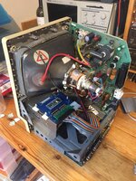
Here's what the final installation in the Plus looks like:
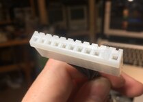
First, the power connector. To do this, I made up a replacement cable between the LB and AB. The connector at each end of these is a 11-position Molex KK396, with one connection blanked off. The cable is just wired straight-through, pin 1 to pin 1, etc. The blanked-off connection is pin 2; I like to use hot glue to make an ad-hoc key. It's not great but it's better than nothing.
At one end of the cable (which will become the analogue board end), crimp two wires into the terminals for 5V, 12V, and the two grounds. One of these should go to the other KK396. The other go to a "Molex" power connector. The result looks like this:
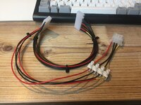
I attached the molex connector with screw terminals because it was what I had handy, and I don't have the tool to crimp my own. You could probably leave out the 12V—you probably wouldn't want to power a spinning HD off the rather anæmic Plus supply—but I am cursed with completionism.
At this point, you should string the cable between the LB and AB and check that the voltages on your new power connector are in the right places.
Now for SCSI data. We have two issues here: how to tap into the SCSI data on the board without modifying it, and how to turn it into the right SCSI pinout.
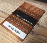
For the first I used one of @Stephen's Cloney Clips. Since I am bad at soldering and have no hand-eye coordination, I adopted a couple of tricks which might also help other people. First, I built a test jig on a bit of veroboard to make sure that I'd got all the pogo pins in at the right height. This is just a spare 40-pin junk chip from something I disassembled years ago and some loops of wire; then I can just methodically walk down the pads on the top of the Cloney Clip and the loops of wire with my multimeter in continuity mode and make sure good connection is being made. Two of the pins I installed did require a second attempt, so this was a major annoyance saver.
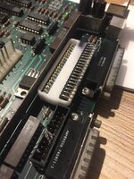
Another thing I am bad at is soldering ribbon cables. However, there's a hack here. There is room to solder on right angle pin headers in a kind of ad-hoc surface mount fashion. This is easier, because the row of pins is rigid, and once you've soldered on one end, the rest stay put. For this use case, you want to solder on a row of them on one side of the clip; this row will go on the side of the chip that is towards the back of the board, thus:
There is then room, if one is careful to put a 20 way ribbon cable from this connector up through the hole in the chassis and up into the main cavity.
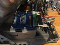
To adapt this ribbon cable into a more useful pinout, I used one of @360alaska's adaptors that were designed for soldering onto the chip. Instead of doing it like this, I soldered on a matching set of right angle pin headers to the pads that would go to the chip. Also, instead of soldering on a male socket to the top of the board to take a cable, I soldered a female plug on the bottom of the board to plug directly into a SCSI device—the device in question being a BlueSCSI (of @Bolle's board design).
So far, it's behaved: I'm a little worried about noise on the SCSI cable given that all the grounds but one have disappeared, but I probably shouldn't be.
I'll keep people updated on how well it works longer-term, but I hope this is interesting to someone, at least.
Here's what the final installation in the Plus looks like:

First, the power connector. To do this, I made up a replacement cable between the LB and AB. The connector at each end of these is a 11-position Molex KK396, with one connection blanked off. The cable is just wired straight-through, pin 1 to pin 1, etc. The blanked-off connection is pin 2; I like to use hot glue to make an ad-hoc key. It's not great but it's better than nothing.
At one end of the cable (which will become the analogue board end), crimp two wires into the terminals for 5V, 12V, and the two grounds. One of these should go to the other KK396. The other go to a "Molex" power connector. The result looks like this:

I attached the molex connector with screw terminals because it was what I had handy, and I don't have the tool to crimp my own. You could probably leave out the 12V—you probably wouldn't want to power a spinning HD off the rather anæmic Plus supply—but I am cursed with completionism.
At this point, you should string the cable between the LB and AB and check that the voltages on your new power connector are in the right places.
Now for SCSI data. We have two issues here: how to tap into the SCSI data on the board without modifying it, and how to turn it into the right SCSI pinout.
For the first I used one of @Stephen's Cloney Clips. Since I am bad at soldering and have no hand-eye coordination, I adopted a couple of tricks which might also help other people. First, I built a test jig on a bit of veroboard to make sure that I'd got all the pogo pins in at the right height. This is just a spare 40-pin junk chip from something I disassembled years ago and some loops of wire; then I can just methodically walk down the pads on the top of the Cloney Clip and the loops of wire with my multimeter in continuity mode and make sure good connection is being made. Two of the pins I installed did require a second attempt, so this was a major annoyance saver.
Another thing I am bad at is soldering ribbon cables. However, there's a hack here. There is room to solder on right angle pin headers in a kind of ad-hoc surface mount fashion. This is easier, because the row of pins is rigid, and once you've soldered on one end, the rest stay put. For this use case, you want to solder on a row of them on one side of the clip; this row will go on the side of the chip that is towards the back of the board, thus:
There is then room, if one is careful to put a 20 way ribbon cable from this connector up through the hole in the chassis and up into the main cavity.
To adapt this ribbon cable into a more useful pinout, I used one of @360alaska's adaptors that were designed for soldering onto the chip. Instead of doing it like this, I soldered on a matching set of right angle pin headers to the pads that would go to the chip. Also, instead of soldering on a male socket to the top of the board to take a cable, I soldered a female plug on the bottom of the board to plug directly into a SCSI device—the device in question being a BlueSCSI (of @Bolle's board design).
So far, it's behaved: I'm a little worried about noise on the SCSI cable given that all the grounds but one have disappeared, but I probably shouldn't be.
I'll keep people updated on how well it works longer-term, but I hope this is interesting to someone, at least.

