superjer2000
Well-known member
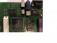
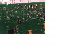
I removed the caps from the logic board of the LC575 I just bought. Before soldering on new caps, I always like to check to ensure that the pads have continuity somewhere else on the board to see if I have to do any jumpering.
The positive leg of C5 and C20 are connected and then C2 connects to a via that goes to the back side of the board. That via must connect to a middle layer in the board as you can't see any traces on either side. I have buzzed the pins of all nearby components and I just can't figure out what the positive side of C5 and C2 connects go (or my trace is broken). Would somebody mind using their continuity checker to see what
C5/C2 should connect to?


