EffingController
Member
Hi everyone! I recently acquired an LC III which I’ve recapped (both the logic board and the power supply). After recapping, the machine will power on, but will not output any video, and only outputs sound via the speaker jack in the back. I get a boot chime which is immediately followed by a Sad Mac chime. This has been consistent despite an alcohol bath and gentle scrub, a new PRAM battery, reseating the ROM, FPU, RAM and VRAM chips in their slots, and trying with various combinations of powered components (HD, fan, etc) unplugged.
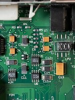
I decided to second-check my recap work and I discovered a possible fault that I need some guidance on. Based on the schematic below, it looks like the positive pad of C5 should have continuity to one side of R7. I don’t get a continuity beep, and when I switch to resistance, I’m getting 1.6 kOhms.

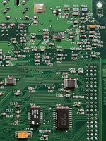
That just so happens to be the resistance rating of the nearby resistors, namely R8. Here’s a picture of the board I’ve been working on. I’ve removed R7 and C5 while I work through this. Based on the photo, I’m not sure the schematic is right (or at least my reading of it). It looks like a trace leads from the right pad of R7 to the left pad of R8. (Sorry I can’t get it any closer, I’m stuck with my phone’s dinky camera.)

Can anyone with a working LC III logic board confirm this? If this isn’t the issue, are there any other suggestions for what I should check next? I’ve checked the voltage under load and everything seems fine. The -5V rail is only at -2V, but as I understand it, that rail is primarily used for AppleTalk; please correct me if I’m wrong!
This is my first restoration project and I am so grateful this place exists. Thanks for any help!
I decided to second-check my recap work and I discovered a possible fault that I need some guidance on. Based on the schematic below, it looks like the positive pad of C5 should have continuity to one side of R7. I don’t get a continuity beep, and when I switch to resistance, I’m getting 1.6 kOhms.
That just so happens to be the resistance rating of the nearby resistors, namely R8. Here’s a picture of the board I’ve been working on. I’ve removed R7 and C5 while I work through this. Based on the photo, I’m not sure the schematic is right (or at least my reading of it). It looks like a trace leads from the right pad of R7 to the left pad of R8. (Sorry I can’t get it any closer, I’m stuck with my phone’s dinky camera.)
Can anyone with a working LC III logic board confirm this? If this isn’t the issue, are there any other suggestions for what I should check next? I’ve checked the voltage under load and everything seems fine. The -5V rail is only at -2V, but as I understand it, that rail is primarily used for AppleTalk; please correct me if I’m wrong!
This is my first restoration project and I am so grateful this place exists. Thanks for any help!
 I hope you can locate it. A good way is to walk around barefoot and wait for it to jam itself in your foot when you least expect it. Speaking of experience here


