• Updated 2023-07-12: Hello, Guest! Welcome back, and be sure to check out this follow-up post about our outage a week or so ago.

Laser 128ex....how to revive

OleLila

Well-known member
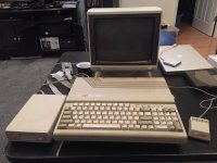
I had a working Laser 128 ex ((Apple IIc clone) that was working fine. The external 3.5 inch drive was not, but I could plug it into the computer and just get an I/O error on APTPro. I disassembled the external drive, unplugging multiple small connections in the process, cleaned, reassembled. The e external drive spun the first time, but no disk recognition. The second time....nothing, no noise, no smoke, no pops....Power LED on computer is on but nothing else, no internal drive noise, no reset with keyboard.

The voltages on the external drive connections are fine. I can use a voltmeter but that’s about it.  I cannot find board diagrams for the Laser 128 to even try and give it a shot. Any advice on where to start? 


bibilit

Well-known member
I think you should have a look inside, hard to say not worked on any of those drives ever.


OleLila

Well-known member
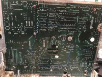
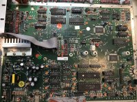
Looked inside...didn't see anything, but did ruin my Apple Iic ROM when I tried it. Heres a couple of pictures of the logic board incase it helps someone. The Laser ROM is on the bottom of the logic board and is accesible  by removing 2 screws.IMG_5277.jpegIMG_5278.jpeg


bibilit

Well-known member
Are you getting something on display ?

from your pictures nothing obvious, but never worked on one of these. 

Are you able to look at voltages ? It will be my first guess. 


OleLila

Well-known member
Nothing on display.....got the 12, 5 and -12 volts on external floppy port; only 12 on the internal floppy port....need to look at/locate the pinouts on  ROM and processor I guess...can acmes the ROM and ports easily but lots and lots of screws to get past shielding to mainboard


OleLila

Well-known member
The ROM on the Apple Iic was fine, I bent a pin on the AE memory expansion board when I replaced it, it works fine after a jumper. 

Since V-tech backwards engineered the Apple IIc ROM for the Laser, can I put the Laser 128 ROM into the Apple Iic and see if it works? Should the Apple Iic ROM work in the Laser?


bibilit

Well-known member
I will not do that, you can ruin for good one or another unit. 

If you Have not all voltages on the internal floppy drive, maybe this one is faulty and preventing the Laser from working. 

From the pictures, the cable cannot be removed from the Logic board without desoldering, is this correct ?


OleLila

Well-known member
Thats correct, the cable is soldered. On the 20 pin ribbon header for internal 5.25 drive, the voltages check out except there is no -12 volts on pin 9. On the external drive port the voltages check out including -12 volts on pin5. On the schematic for the internal connector, pin 9 is drawn with -12 volts that ends in a signal ground (hollow triangle).

I stretched my brain and in fact was able to locate schematics in the back of the Laser series technical manual, it takes a few minutes to download.

http://www.progettosnaps.net/manuals/pdf/laser128.pdf


bibilit

Well-known member
Are you able to check cpu clock and reset line ?

from my quick reading MMU is responsible for the correct cpu clock (pin 34) to the CPU. 

You will probably need a probe and oscilloscope here. 


bibilit

Well-known member
So, checking at schematics, i can confirm that the clock goes from the MMU (pin 34) to pin 37 of the CPU ( 00 in) 

The reset line of the CPU is on pin 40.

The schematics can be misleading, here are the schematics for the 65C02 :

https://downloads.reactivemicro.com/Electronics/CPU/65C02%20Datasheet.pdf

Also, the floppy drive is soldered on one side, but apparently connected on the other side (correct ?) what happens when te drive is disconnected ?


OleLila

Well-known member
I just obtained an oscilloscope in the last few days and currently waiting for the probes. When the probes arrive, it will be my first time using an oscilloscope. I will have the equipment "to check cpu clock and reset line", but not sure what the phrase actually means. 

One end of the internal disk drive cable is soldered to the mainboard and the other end does have a plug (same with keyboard cable). The computer behaves the same when the internal disk is unplugged: power LED on, totally quiet, no video.

Thank you for looking at this. headed to 65C02 schematics and to find info on probing MMU now.

The - 12 volts on pin 9 of the internal drive  I had in the above post looks wrong...I got that value from the internal IIc connector....pin 9 on J11 (internal drive) for the Laser is SIDSEL.

 
Last edited by a moderator:

IlikeTech

Well-known member
The clock pin should have a 1.023 MHz square wave on it, and the reset line should stay low for around a second after the switch is turned on, and then go high.


bibilit

Well-known member
Most of my troubleshooting has been done using a logic probe, so if you have an oscilloscope or close to, you will have a better tool anyway.
65c02_pinout.png.7c460fb0db38e6b512f9d00c666b12c7.png


And yes, IlikeTech is right, you are looking for some information about what kind of information the CPU is getting from the rest of the components nearby.

The CPU is expecting a 1 Mhz clock signal on pin 37 (here above PHI IN) so the Oscilloscope should be able to detect this information.

The reset line, well has said before, should be low voltage when switching the power ON then change status to high after a second (pin 40)

You can also check voltages to the CPU (VSS is Ground for your understanding, and present on pin 21 and 1) while VCC (pin 8 is supply voltage (5 volts more or less 5 %)

So using a multimeter you can already check a clean input of 5 volts between pin 8 and 1 / or pin 8 and 21.

Then still using the oscilloscope, check output clock signals (Pin 3 and 39) according to the information supplied concerning the 65C02 (pin 39 is output 2 and should have the same square wave seen before on the input clock signal (pin 37) while output 1 (pin 3) should still have a similar wave but out of phase by 180 °.

Still, you can also have a Look at the Address lines (from A0 to A15) and Data lines (from D0 to D7) for some activity.

Last point, when shorted some chips are very hot, so leaving the system on for a while and touching the chips with your fingers can give you a clue of the problem.

 
Last edited by a moderator:

OleLila

Well-known member
OK....lots of screws and sheildng to remove. Will check the CPU voltages and wait for oscilloscope probes. Everytime I flip the solder cable over or remove the sheilding , feel like I'm on borrowed time waiting for something to give.

Just to be clear....for instance...ground probe to ground and positive probe to CPU pin 37, auto detect and look for 1 mHz wave?

 
Last edited by a moderator:

bibilit

Well-known member
On the 20 pin ribbon header for internal 5.25 drive, the voltages check out except there is no -12 volts on pin 9. On the external drive port the voltages check out including -12 volts on pin5. On the schematic for the internal connector, pin 9 is drawn with -12 volts that ends in a signal ground (hollow triangle).
Wait, looking at the schematics once again, while the external drive has a - 12 volt line on pin 5, the internal one (connector J 11) has no - 12 volt line apparently, and pin 9 goes to SIDSEL (2) (there is probably a capacitor and inductor in between, but no - 12 volt expected)


OleLila

Well-known member
Alright...so the power voltages on the CPU as above checked out; also went to obvious components on the schematics and checked out voltage and grounds which seemed ok....5 volts all around. . The onboard ram showed a plus 5 volt at pin 8 and grounded at pin 18....different than the ram on expansion card but I cannot really interpret the schematic regarding the onboard RAM. I did note that pin 40 on the CPU went to 5 volts (no delay at all) as fast as pin 8....pretty much instantaneously ramps up after flipping the on switch.

Left it turned on for a while, I wouldn't call any components hot...the only ones that felt even a little warm were the RAM and CPU.

Looked through the tech manual above and printed out several enlargements of the schematics.  There is  pretty remarkable detail regarding timing and frequencies in Chapter 11 hardware implementation. Will probably have the oscilloscope probes on tuesday...not sure when I'll have change to try this again though.

 
Top