alectrona6400
Well-known member
Hello!! If you don't know I'm simply someone who likes messing with old electronics.
Back in March of 2023, someone in a Discord server I was once in was giving away some parts of their collection, and I was lucky enough to call dibs on a Macintosh SE/30 with a RasterOps Colorboard/264. Just one catch: all machines were being sent away as-is, and obviously that includes the gamble of bombed or not bombed.
This is a story of be doing a couple stupid things early on, and more recently, a work-in-progress resurrection.


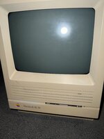
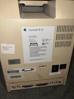
^ This is the machine when I first got it. It looks a bit worse than it does on camera, because the case is yellowed and a small part of it had been chipped off at some point. Not sure if I will ever have the equipment to do retr0brighting since I'm a disorganized mess, but at least it isn't horrible...
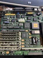
The board however is a different story. THANKFULLY, it wasn't battery bombed. However, this wouldn't be a vintage electronics repair without multiple failed capacitors and chips. And of course, this wouldn't be a typical Katheryn repair job without screwing up;ask me how I know...
Oh well. Practice makes perfect. Anyways, I did get the capacitors replaced, and the machine did boot! But then I noticed something very wrong... the floppy drive didn't work. Also, I had to remove the Colorboard to even get the machine to work, and upon further inspection some traces might be shot. Fun.
So what did I do to try fixing the problem with the floppy drive? Assume the worst and remove SEVERAL of the QFP chips that were near the ports. Tried soldering them back on and got the infamous Simasimac; I am by no means surprised by my own stupidity. And my crappy soldering equipment. Some of you may have seen a thread about solder pads being ripped off. And honestly, now that I think of it, I blame the capacitors too; I believe those leaking have caused some areas to be weaker. I could be very wrong, but that's also why this board had trouble working. A lot of the solder joints on the board were tainted, and were not something that was easy to fix.
So I put the project on hold for 11 months. Recently, I wanted to gather the parts for it since I was thinking of resurrecting it after almost a year of it not working. I could have repaired the original motherboard, but I wanted to start over essentially. I wanted to ensure that I would have a board that wasn't going to potentially develop MORE problems, and also something with fresh, clean, and most importantly, serviceable soldering. A lot of those original joints were PAINFUL to work with, at least with how I did it earlier.
Recently, I kinda went into panic mode thinking if I would EVER finish this project. As many of you know, the SE/30 is one of the most highly sought-after computers ever made. Yeah, this is NOT your average compact mac! Sure, the Classic II sounds like it's equivalent on paper, but oh ho ho... believe me, it is not.~
Mercifully, @jajan547 had reached out to me saying they had a spare SE/30 Reloaded board they could sell me. Moments later, I bought it, and recently, I have worked tirelessly on it.

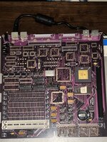
After some preparation, a bag of Jolly Time Blast O' Butter (not sponsored lmao), and ensuring I won't die from lead poisoning by allowing proper ventilation in my room, I set off to work and so far, this is how far I've managed to come. I'll need to buy parts for the board since not everything is just going to slot right in. I had to wrestle the donor a bit to get some parts off, but so far I am pleased with how this is going. The PLCC sockets weren't put on by me as were 90% of the passives under the board (I did transfer the ferrite beads), but it honestly looks great so far! And the pads are something I WON'T suffer with! Though I am curious, where could I find PLCC sockets for all the QFP chips and what ROM chips could I find? Ideally, I would like a 32-bit clean ROM.
More coming later. I have a busy life and honestly I procrastinated a bit to do some work on this. :^))
Back in March of 2023, someone in a Discord server I was once in was giving away some parts of their collection, and I was lucky enough to call dibs on a Macintosh SE/30 with a RasterOps Colorboard/264. Just one catch: all machines were being sent away as-is, and obviously that includes the gamble of bombed or not bombed.
This is a story of be doing a couple stupid things early on, and more recently, a work-in-progress resurrection.


^ This is the machine when I first got it. It looks a bit worse than it does on camera, because the case is yellowed and a small part of it had been chipped off at some point. Not sure if I will ever have the equipment to do retr0brighting since I'm a disorganized mess, but at least it isn't horrible...
The board however is a different story. THANKFULLY, it wasn't battery bombed. However, this wouldn't be a vintage electronics repair without multiple failed capacitors and chips. And of course, this wouldn't be a typical Katheryn repair job without screwing up;
Oh well. Practice makes perfect. Anyways, I did get the capacitors replaced, and the machine did boot! But then I noticed something very wrong... the floppy drive didn't work. Also, I had to remove the Colorboard to even get the machine to work, and upon further inspection some traces might be shot. Fun.
So what did I do to try fixing the problem with the floppy drive? Assume the worst and remove SEVERAL of the QFP chips that were near the ports. Tried soldering them back on and got the infamous Simasimac; I am by no means surprised by my own stupidity. And my crappy soldering equipment. Some of you may have seen a thread about solder pads being ripped off. And honestly, now that I think of it, I blame the capacitors too; I believe those leaking have caused some areas to be weaker. I could be very wrong, but that's also why this board had trouble working. A lot of the solder joints on the board were tainted, and were not something that was easy to fix.
So I put the project on hold for 11 months. Recently, I wanted to gather the parts for it since I was thinking of resurrecting it after almost a year of it not working. I could have repaired the original motherboard, but I wanted to start over essentially. I wanted to ensure that I would have a board that wasn't going to potentially develop MORE problems, and also something with fresh, clean, and most importantly, serviceable soldering. A lot of those original joints were PAINFUL to work with, at least with how I did it earlier.
Recently, I kinda went into panic mode thinking if I would EVER finish this project. As many of you know, the SE/30 is one of the most highly sought-after computers ever made. Yeah, this is NOT your average compact mac! Sure, the Classic II sounds like it's equivalent on paper, but oh ho ho... believe me, it is not.~
Mercifully, @jajan547 had reached out to me saying they had a spare SE/30 Reloaded board they could sell me. Moments later, I bought it, and recently, I have worked tirelessly on it.

After some preparation, a bag of Jolly Time Blast O' Butter (not sponsored lmao), and ensuring I won't die from lead poisoning by allowing proper ventilation in my room, I set off to work and so far, this is how far I've managed to come. I'll need to buy parts for the board since not everything is just going to slot right in. I had to wrestle the donor a bit to get some parts off, but so far I am pleased with how this is going. The PLCC sockets weren't put on by me as were 90% of the passives under the board (I did transfer the ferrite beads), but it honestly looks great so far! And the pads are something I WON'T suffer with! Though I am curious, where could I find PLCC sockets for all the QFP chips and what ROM chips could I find? Ideally, I would like a 32-bit clean ROM.
More coming later. I have a busy life and honestly I procrastinated a bit to do some work on this. :^))
