• Updated 2023-07-12: Hello, Guest! Welcome back, and be sure to check out this follow-up post about our outage a week or so ago.

I want to do this...

MinerAl

Well-known member
Progress... in the form of gathering a bunch of the parts into the same room.

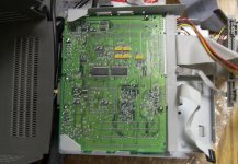
The 575 board and end-connector will be perfect. Like, frighteningly perfect. Like, maybe the original Color Classic was supposed to be in the Classic II chassis perfect. All I need to do is mark where the notches in the sheet metal (for the end-connector to slide into) should be and have my brother-in-law punch them out for me.

There are a couple of metal loop standoffs on the bottom of the board that I'll need to nip to let it slide in. There is no way anything will be useful in the comm-slot :-/ There is just barely (you might say: exactly) enough clearance for the LCPDS card though, so it will be networkable.

This connector/cable-loom is way too much for this project. I really need an original Color Classic loom with a single regular 50-pin socket instead of the card-end silliness. I can make this work, though. I hope.

575inClassy.jpg


MinerAl

Well-known member
Moving on, I will need to get the video signals out of the loom's Analog Board connector.

The following is stolen from the Frogeye link earlier in this thread.

PCC02.jpg


Analog
Connector/

Ribbon

Position Signal

-------------------------

1 = -12 V input

2 = GND

5 = ADB Power supply

6 = GND

7 = Power off command

8 = GND

9 = Composite signal out*

10 = GND

11 = BLUE out*

12 = GND

13 = GREEN out*

14 = GND

15 = RED out*

17 = Brightness control output

18 = GND

19 = Contrast control output

20 = Monitor ID 2*

21 = Audio in (Mic)

22 = GND

23 = +5 V

24 = Monitor ID 1*

25 = Monitor ID 0*

28 = Audio out ®*

29 = GND*

30 = Audio out (L)*

31 = GND*

37 = Sound amplifier control output

My assumption is that I can follow the ribbon cable back to the logic board connector and take the signals (video and audio, *'d above) right off the main connector, and not have the analog board connector any more at all.

Since I'm not using the control panels that the CC/5xx/6xx machines had on the front, I shouldn't have to connect them to anything from the logic board connector, right?

Then I can take the appropriate +12 V, +5 V, and GND signals off the LC-475 power supply right into the logic board connector.

I'm going to remove the superflous CD-ROM cabling, and possibly crimp a standard SCSI 50-position connector and 4-position molex connector on the end of the SCSI HD ribbon. That will almost make this 550 loom a CC loom!


techknight

Well-known member
Way back in the day, I had an old PM5300 with a dead flyback and no video connector, I was able to pull out the video signals from the loom and run it into a VGA monitor, and never had any issues. it was a huge mess. but it worked.


MinerAl

Well-known member
Yup. As long as this idea has taken to come to reality, coming up on a year or so, I've had plenty of time to change everything about the insides.

The 575 board is still very much true to the original concept. Still a 33MHz Quadra brain, still capable of grayscale VGA+, Ethernet, etc. But I (we) were jumping through all kinds of hoops to get the 605's brain in there without changing up the case's bucket. I decided after the relative success of the face-lift, a butt-lift wouldn't be too traumatic, so I (we) no longer had to worry about making a stealth port board. Everything about the 575 fits so much better in the original rails, like to the point (as I mentioned earlier) that I wouldn't be surprised if the CC board was intended for something very-much-closer to the original Classic case in the first place. I'm already relatively comfortable with manipulating the wire-loom from my decade-ago adventure in Zip-ifying a CC, so I can hopefully accomplish most of the rest of this myself.

My question now: The loom has composite sync. How shall I deal with that?


Trash80toHP_Mini

NIGHT STALKER
Got it, maybe? You're replacing the port section of the Classic's derriere with that of the 575?

As far as your video predicament goes, methinks the video-out card of a Quadra 630 or its RoadApple 6xxx offspring wired up to the loom might be all that you'd need.

Do I recall you saying something about not being able to use the Comm Slot for EtherNet? You(we :lol: ) just can't have that now can we?

There's got to be a way to fit the KVMage in there much more easily with all that extra room and customized @$$plate. [;)] ]'>

I've got a Radius Pivot LC Card of some sort for a second monitor somewhere around here. It's not in the Magic Plastic Shoe Box of PDS Goodness, so I'll have to check the pile-o-LC slotted macs. I'm guessing macmetex still has some of these kicking around.

Heh! [}:)] ]'>


MinerAl

Well-known member
Yup. This'll pretty much be a monochrome Takky hack. (Blakky?) Some careful carving on the Classic rear end and the 575 back-door should result in a decent rear view. (Cool side effect, I should be able to slide out the logic-board like a real CC-6500 Mac).

I'm really hoping to use the pseudo-LCPDS slot for Ethernet. It'll take some heavy duty metal-cutting to make a place for the Comm-Slot to work. Might not be the worst though, it would make the butt-lift part of the plastic-surgery better looking if the com-slot port was populated/populatable.

If I go with a LCPDS vid-card, I'm right back where I was with having the video port sticking out the back. Might as well just use the 605 board at that point. There were some composite video out Macs (IIcx/ci?) that were able to be adapter'd to VGA. I'll have to look into how those adapters were wired.


Trash80toHP_Mini

NIGHT STALKER
I know somebody who likes playing with his pneumatic sheet metal working tool collection almost as much as his Japanese pull saws. [:)] ]'>

I don't understand the problem with the video in port, it should be an easy hack if you're using a Comm Slot NIC and an LC VidCard . . .

. . . remove one of the mounting lug nuts on the VidCard . . .

. . . drill the lug nut hole in the DA-19 connector/Backplane plate out to 3/16" diameter . . .

. . . remove the mounting bolt from your VGA adapter for the LC VidCard . . . funnel shaped Mac VDO type adapter preferably

. . . drill the mounting bolt hole of the adapter out to the same diameter . . .

. . . lop off one end of a thin VGA cable like the one in my hand . . .

. . . feed it through the 3/16" holes and terminate it to a 15-20 pin male<->female plug kind of deal . . .

. . . terminate the short, lopped off part of the VGA cable to the matching socket/plug . . .

All you need to do is unplug the connection and when you pull out your drawer. and it's free and clear.

The card will be removable from the MoBo as well. One mounting lug is plenty for the VGA adapter, it seems like a quarter of my macs are missing one side or the other. Remove the RFI shielding from the LC Card cutout and the Mac VDO fits through vertically just fine. Horizontally you'll only only need to file the tiniest smidge off each side of the plastic shroud. The VGA cable's connector and Ferrite ring on the cable fit through without modification.

If you decide to change out the LC PDS Card, all you need to do is unhook the VGA-out cable from the adapter, unscrew the intact mounting bolt of the VGA adapter, pull through a bit of the slack on the VGA-in cable, pop off the card and the feed the VGA Adapter and its VGA cable tail through the slot access hole.

Did I mention the guy I know with the Japanese pull saws has pneumatic drills, a thin VGA cable and a Mac VDO adapter? [}:)] ]'>


MinerAl

Well-known member
I may take you up on carving a chassis-channel for the comm-slot, but I'm going to exhaust my options with the on-board 575 video before I go shopping for more cards.

If i wanted to pipe cables back into the case, I would just use the 605 board and save the hassle of messing with the wiring loom.

Or... damn it ...use the 605 board, have a VGA-in port for the monitor up in the Classic's adjustment panel area (where the 128-Plus's battery compartment was), and then I wouldn't need to worry about a KVM. Just a nice thin custom/perfect length DA-15 to HD-15 cable to send video up from the Quadra when wanted, and a cable swap away from being an external monitor for anything.

If I decide to abandon the original concept of "what a '94 Mac Classic should've been," I'll do that. I really like the idea of it being more than just a cosmetic hack. A complete product. I'm all philosophical about it :)


Trash80toHP_Mini

NIGHT STALKER
Cool beans, loopback sounds good, but KVM . . .

. . . I just can't leave that kind of challenge alone. ::)

< . . . wonders about suggesting an external KVM setup to KIS . . . nah! }:) >

. . . I'm going to exhaust my options with the on-board 575 video before I go shopping for more cards.
The onboard video will be better anyway, it's all about having two screens, now a GS Classic/Color FPD LCD combo . . . ;D


MinerAl

Well-known member
As I mentioned in the WTB thread, I've hit a snag and may have to reconstruct the %*$#@ 550 wiring loom I have. I've taken the SCSI ribbon off of a Color Classic connector and replaced it before, so I stupidly assumed I could repeat the process with the 550's. Stripped several metal contacts out of the connector. I said bad words. There are plenty of spares in the mess here, but reconstructing it will be a bummer. I really wanted to be done by the 11th of Dec.

In good news: the sanding is done. The face is ready to paint. I'll share pics when it's beautiful.

I need to do some bucket plastic surgery now. I'm going to cut out a door sized hole in the back for the cut down port cover from the 575, and drill the 31 hole starburst in the right side for the other stereo speaker.

I've decided to not make a channel for the comm-slot in the metal chassis. It would weaken the chassis, and there's not really room for it on the back face of the bucket without moving the power port and switch. I do still need to notch the chassis where the board-wide connector will need to lock in. I'll do the bucket work first so everything lines up perfectly.

I need to decide if I'm going to cut down the analogue board to just the power port and switch, or if I'm going to just float all the unnecessary electronics off of it leaving a full sized but mostly empty green board on the left side of the case. Either way I need to lose all those extra bits for space. I may be able to mount the HDD on the cleared off AB.

Then paint the plastics, cram everything in there and pray I didn't ruin anything in the year this hack's taking.


CC_333

Well-known member
Was the analog board from a Classic I or II?

I'd be interested in all the "unnecessary electronics".

Meanwhile, I'm looking forward to pictures!

c


Trash80toHP_Mini

NIGHT STALKER
I still don't understand why you don't just desloder that entire connector and then hardwire every signal to where it's supposed to go. They're all lined up for you to use ribbon cable wired directly into the through holes in every case.

:?:


MinerAl

Well-known member
You mean on the 605 board? Yeah that would work, and if this 575 loom trick doesn't work out I will probably go back to that. It's just so elegant to have the back door and the slide in lobo. I'm kind of in love with this 575 board at the moment, but if the video issues are too big a deal, I'll go back to the 605 board. The port holes would be much harder to get right. I don't have a good LC butt to graft on a Classic case.


MinerAl

Well-known member
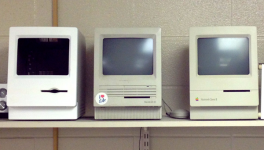
Just a paint job and decals away... (on the outside)

siblings.png

(The SE got its sticker after being rescued from it's position as a doorstop. Worked well at the time; needs a recap now. :-/ )

 
Top