• Updated 2023-07-12: Hello, Guest! Welcome back, and be sure to check out this follow-up post about our outage a week or so ago.

Floppy / Floppy Controller SWIM Issues

pgreenland

Well-known member
Solved!

I took a step back over Christmas and had a nose around the schematic again, looking for places where logic between the RAM and the floppy disk meets.

One of the PALs, UH7, manages the write signals to the RAM banks. As well as inverting the write signal from the floppy controller. The write signal that goes off to the drive that is, meaning it's only active during a disk write.

Dropping the logic analyser on the legs of the chip all looked normal and at the same time the problem was gone.

Removing the logic analyser, the problem was back.

Took the chip off, cleaned up the pads, gave everything a good IPA bath and resoldered.

10 floppies written without an error and booting from floppy is now a thing again.

Thanks for the input over the last few months everyone.....it can finally go back in its case at last :)

Two recapped and fully operational again....two to go :p
 

jmacz

Well-known member
@pgreenland I've got a similar issue with an SE/30 where I can read from the floppy drive no issues, write has corruption, and a format causes a crash (address/bus errors).

Covered the basics, toned things out, everything looks ok as far as I can tell. Was about to head into deeper debugging and stumbled upon this thread from a little over a year ago.

I wanted to check back in and see if your SE/30 is doing ok after the change you made above? And also, I wanted to see if after you pulled UH7 whether you were able to determine what was wrong? Or did cleaning it after you removed it magically solve the issue?

Toned out all the pins and that seems fine. Will probably put logic analyzer probes on it next but was curious, when you said "dropping the logic analyser on the legs of the chip", did you put a probe on all 20 pins or particular ones? and any idea what caused it to work after you did that?

Hoping to save some time by leveraging your effort :) Thanks!

Oh and should clarify, my board did not have a battery leak, but did have capacitor leakage. The logic board, analog board, PSUs are all recapped and the analog board/PSU tested out fine in another machine.
 

pgreenland

Well-known member
Hey,

Yep, it's been fine till this day....well it's developed RAM problems since, but the floppy always works :p

I was nosing around with the logic analyser trying to find a bad chip. It took me way too long to spot that the write signal was generated by UH7 from a couple of other signals.

Took the chip off, wasn't anything interesting under it from memory. The legs were in a semi-bad state though. Originally I believe applying pressure to it resolved it for periods. Removing, cleaning the legs of the chip and socketing it sorted it out.

I might have got away with trying to reflow just the few pins involved but was planning on building one of bolle's boards for a more damaged machine, so kinda wanted to see how hard the big plcc packages were to desolder and clean up.

With hot air it's pretty easy, if you take your time. Trying to reflow the pins with a regular iron might be an option, or giving the area of the board a scrub with some IPA just in case there's anything hiding around the chip.

Hope you get it sorted and its something as simple as a bad joint.

Thanks,

Phil
 

jmacz

Well-known member
Ok got it. Thanks for the details.

I need to narrow down where the corruption is as there's definitely address/bus errors only when formatting. Everything toned out and the WR/WR* signals on UH7 looked fine under a logic analyzer. Will have to finish examining all the other lines.
 

jmacz

Well-known member
Wow...

I put some probes on the board to watch the signals as I attempted to format a floppy. I had a probe on UH7 pins 4 (WR*) and 16 (WR). Also had probes on the SWIM chip UJ11 pins 2 (WR*) and 20 (ENABL1) as well as on the J8 connector pin 18 to watch the writes.

It magically started working. I was able to consistently format disks. Exactly what you saw @pgreenland.

I then removed the probe on the J8 connector. Still working. Removed the probes on the SWIM chip. Still working. Removed the probe on UH7 pin 16. Still working. Removed the probe on UH7 pin 4... still working... but... the second attempt to format after I removed that last probe failed. And then it was failing again. Not as bad as the outright crash on format. But still failing to initialize nonetheless.

I then put the probe back on pin 4. Started working again.

I then removed all the probes and the logic analyzer. And just used a pair of tweezers to apply pressure on UH7 pin 4. Worked. Remove the pressure. Starts failing.

So it looks to be a bad contact. I tried reflowing that one pin but that didn't help. I still need to apply pressure and if I do so, format works consistently.

I will have to remove that chip this weekend, clean it up, and resolder.

I'm curious whether the same issue is occurring (I see multiple threads on this) because that UH7 chip happens to be dead center on the board. And as the board is handled, I'm curious whether there's a lot of pressure applied right where UH7 pin 4 is causing joint failures.
 

jmacz

Well-known member
And it gets stranger...

I pulled UH7 off the board and the chip itself and its legs look fine. Nothing remarkable underneath the chip either. No breaks. Everything is clean and pristine. I cleaned off the pads, cleaned the legs, and soldered the chip back on the board.

Still having issues.

I then placed pressure back on pin 4. Works. Removed pressure, doesn't work. I placed pressure on other pins. Doesn't work. Placed pressure back on pin 4. Works. So I figured the pin must be broken within the UH7 chip. But that doesn't make sense as my logic analyzer says pin 4 and pin 16 are working properly (UH7 is inverting the signal between those pins). And again, placing the probes on those pins and it works. Is it really the pressure?

So removed the logic analyzer again. Applied pressure on pin 4, hmm doesn't work.... what?? then I looked down and realized I grabbed a different tweezer to apply pressure on the pin. The I was using had a ceramic tip. It doesn't work applying pressure with a ceramic tip. I grabbed the original tweezer I was using which has a metal tip. Applied pressure. Works. What??

So then I stopped applying pressure and just made contact with my tweezer (which is not touching anything else but my hand) to pin 4. Works. Umm... so pin 4 is connected to a nearby via. Made contact with my tweezer on that via instead. Works. Removed contact. Doesn't work... hmm... UH7 pin 4 is connected to SWIM pin 2. So made contact with my tweezer on pin 2. Works. SWIM pin 2 is connected to a nearby via, so made contact with that via and my tweezer. Works. Remove contact. Doesn't work. WTF?

Then instead of my metal tweezer, made contact with that same via near SWIM pin 2 with a 3" wire (only one end on the via and the other end floating/disconnected). Works. Remove the wire. Doesn't work.

I have no idea what's going on... something is wrong somewhere and it's possible the presence of something conductive is adding something that causes it to work. But I can’t measure it because once I add a probe to observe, it works. It doesn't fail.

I found this thread where someone is having a similar experience on that pin 4:


Argh.
 
Last edited:

jmacz

Well-known member
Formatted a bunch of floppies perfectly with no flaws if I leave a dangling wire connected to pin 4. Without that wire, failures every time. There's no in between.

Dangling a wire on pin 16 doesn't do anything. So it's purely between UH7 pin 4 and SWIM pin 2.

Other tests:
  • UH7 grounds look good.
  • UH7 vcc looks good.
  • Connection between UH7 pin 4 and SWIM pin 2 looks good.
  • SWIM grounds look good.
  • SWIM vcc looks good.
  • My grounds on the board look good.
  • My voltages coming into the board all look good.
For this particular function (formatting a floppy), the only function UH7 provides seems to be inverting the WR signal. Not very complicated. So at this point the only thing I can think that is wrong is the SWIM chip itself.

My issues don't occur during floppy reads. They all occur during writes, specifically during a format/erase of a floppy. And what happens is one of three things: 1.) initialization failure 2.) crash via an address error or a bus error 3.) lock up / freeze with no cursor movement.

The SWIM chip does access the address/data lines. It must be malfunctioning during a floppy write and potentially causing memory errors as well.

I guess I'll have to try something I was hoping to avoid. I will have to pull the SWIM chip off my second IIci and try it on the SE/30 board.
 

cheesestraws

Well-known member
I have no idea what's going on... something is wrong somewhere and it's possible the presence of something conductive is adding something that causes it to work. But I can’t measure it because once I add a probe to observe, it works. It doesn't fail.

Is there meant to be a capacitor between this pin and.... anywhere else, really (probably GND)? If so, look at that. When you touch the joint you're essentially becoming one plate of a tiny capacitor between that pin and ground: I wonder if that chip for whatever reason wants more capacitance than it's getting.
 

jmacz

Well-known member
The various SE/30 schematics all show a single direct connection between SWIM pin 2 and UH7 pin 4. On the other side of the inverter, there's a 33pF capacitor (C67) and I had pulled that one off the board to test it and it checked out. I don't see anything else. Of course, these schematics have had errors in the past.

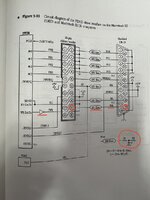
What's interesting is that there's a schematic specifically for the SE/30 inside the Guide to the Macintosh Family Hardware book (second edition pg 351) and that schematic differs from the Bomarc and other schematics online. The GMFH shows the WR signal going through the RP10 Bourns Filters but the Bomarc and other schematics show the WR signal bypassing it. What I actually see on my board matches Bomarc and the other schematics and does not match GMFH.

Regardless, I also checked the Bourns Filters and they seem ok, resistance checks out, no shorts to ground, etc.


Diagram in GMFH:

IMG_6969.JPG

In this diagram, the WR from the external floppy DB19 connector goes through a Bourns filter to pin 18 on the internal floppy connector which then goes through an inverter to the SWIM chip.


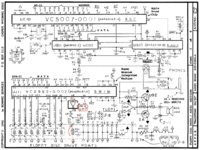
Bomarc Schematic:

Screenshot 2024-02-10 at 9.10.10 AM.png

Here you see the WR from the external floppy DB19 connector going through the 22 ohm R30 resistor, meets up with the C67 33pF capacitor (other side is ground), which then goes through the L22 inductor, to pin 16 of UH7 which inverts the signal, which comes out pin 4 and directly goes to pin 2 on the SWIM.


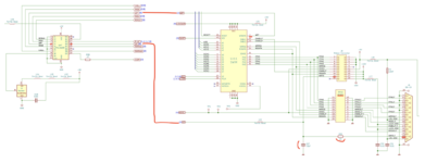
KiKad Schematic (found online):

Screenshot 2024-02-10 at 9.10.45 AM.png

This schematic I found online matches the Bomarc one.


Reality:

What I see on my board matches the Bomarc and KiKad schematic, not the Apple GFMH book schematic.
 

jmacz

Well-known member
Swapped the SWIM chip and that did not help, so the SWIM chip must be ok (I will confirm by moving the one from the SE/30 into my IIci).

Also replaced the C67 capacitor and the R30 resistor. That also did not help.

L22 is a ferrite bead and it's got near zero resistance and has connectivity so should be fine.

The only that works is a dangling wire hanging off of either SWIM pin 2 or UH7 pin 4.

At this point I'm guessing the connection between SWIM pin 2 and UH7 pin 4 (which is inside the board) is shorted somewhere. I checked most of the address lines, data lines, and anything else that seems to cross the path between the SWIM and UH7 chips but nothing obvious turned up.

Next thing to try is to lift SWIM pin 2 and UH7 pin 4 and then run a direct wire between those and see what happens which should resolve it but we'll see.
 

jmacz

Well-known member
(didn't mean to hijack this thread, but the issue was related and hopefully someone in the future can make use of this info)

Solved.

A direct connection from SWIM pin 2 to UH7 pin 4 did not help. Same problem. So given I ruled out the SWIM chip, ruled out the simple connection between the SWIM chip and UH7, the only remaining thing could be UH7 itself.

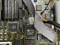
At least from the schematic, it looks like the floppy writes are only using a simple inverter inside UH7 and nothing else. So I wired up a separate inverter using a SN74LVC1G04DBVR I had lying around and that worked!

IMG_6992.JPG

Sorry for the blurry picture, didn't realize it until after I uploaded it. I have made a dozen floppies with no issues. So looks like something went bad with UH7. Nothing else seems impacted though outside of the inverter. I have run many iterations of MacTest Pro and it's all clean. I'm hoping this resolves my issue but will try and produce a new UH7 using Bolle's reverse engineering work as part of his SE/30 board.
 
Top