• Updated 2023-07-12: Hello, Guest! Welcome back, and be sure to check out this follow-up post about our outage a week or so ago.

DIY Localtalk - Ethernet converter

bd1308

Well-known member
The phonenet adaptor takes those TX/RX pairs and combines them into a single TX/RX pair. It's rather a simple schematic to look at, yet it works perfectly.

I think I'm going to see if wiring that port up RS232 fashion works -- if it does then I kinda know that this might work out. I'm just looking for a bunch of crap to go over the lines. Then I can actually figure out what all that means. I'm also hoping the INside Appletalk book will help too -- it better for $36

edit: it didnt make sense

 
Last edited by a moderator:

techknight

Well-known member
Well, localtalk is LLAP. Its defined in that standard how it talks on the port.

So all an ethernet adapter is, is an LLAP to Ethernet translator.

So what you need to do is lookup LLAP and find out how it is framed, etc... and use the arduino to decode it. Phone-Net appears to convert the RS422 full duplex bus into a single RS-485 half-duplex bus system.

So all you need is to setup the localtalk bus as half-duplex with only D+ and D- lines. Then hook these into a regular MAX488 or an ADM483 transceiver, to the AVR.

That will establish something that can listen/talk on the bus. BUT you need to come up with a way to decode the databits on the bus, which is all in the LLAP standard.


techknight

Well-known member
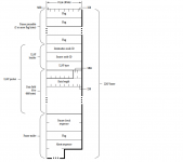
Here is an LLAP Data frame:

The Flags bytes are 0x7E. Communication follows CSMA/CD

The modulation technique I dont know.

data frame.png

 
Last edited by a moderator:

bd1308

Well-known member
Yeah for that part I've already realized I'll need to buy a MAX488 or similiar.

Yeah decoding the transmissions is something that was an obvious plan item (and a big one at that) but I hadn't gotten there. Gotta get PHY done first, then work backwards.


techknight

Well-known member
More information:

Localtalk uses 230.4KBps Biphase space encoding (FM0 encoding) over the RS-422/RS-485 differential pair.

Known as SDLC or Synchronous Data Link Control.

Bit timing is 4.34uS. a 1 bit is a full state for each bit period. It will either be high, or low for the entire 4.34uS duration of the bit timing.

A 0 bit produces a high/low transition exactly half-bit timing, or double the frequency of 1.

Bi-Phase Space

Level change occurs at the beginning of every bit period

"One" is represented by no midbit level change

"Zero" is represented by a midbit level change.

biph-s.gif.65749502a1d047e06e9cb4c37315d8a2.gif


This is why LLAP uses Synchronization via the Flag Bytes, 0x7E.

You have to setup a timer in the AVR using 4.34uS data bit timings. Problem is, You dont know when the "start" condition of a byte occurs. So to get around that, they used the flag byte to synchronize when the first bit of a byte occured.

The easiest thing to do is setup the AVR for pin-change interrupt. Use the timer to keep track of the periods between transitions, then you will know when 1 bits and 0 bits occur. Then you will use the 0x7E to keep track of start/stop of databytes.

For example, when the pin-change interrupt occurs, setup the timer at 0. it will count until the next transition. If the timer counted 4.34uS, that was a 1 bit. if it counted 2.17uS, it was a 0 bit. The first 8 bits received are stored. and checked against 0x7E. Of course it wont be correct because your not synchronized. Thats why the Flag Byte is send multiple times. Once you are able to get enough bits received, you can figure out where your start bit is supposed to be. Fix your start position in the code, and boom now your synched. Now of course youll have to correct in code for double transitions otherwise youll end up with false bits and more bits than you need. hehe.

Simple.

 
Last edited by a moderator:

bd1308

Well-known member
Okay I wonder if I can forget the RS232 stuff because its worthless to me anyway in this project, and just write some code for the arduino to look at data coming in from the PWM pins -- I really could use a logic analyzer but the salae logic is like $199 which is a little out of my range right now (saving for a house down payment this year). I'm going to write something to monitor the D+/D- lines and see what I get. I dont know for sure if I can make a tight enough C++ loop to get down to the 4us range, but it wouldn't hurt trying either.

I dont know what I was thinking trying to wire this up 232 style. Thanks for turning me in the right direction.


techknight

Well-known member
Once you have the entire frame stored in the AVR's RAM, its your discretion what you do with that frame. Send it over RS232 serial, or send it over bluetooth. Or send it over encapsulated UDP/TCP to another end.

Or convert it from LLAP to Ethertalk. Once you get the inside appletalk im sure it has ethertalk in it. But since AVRs are sorta slow, the best thing to do is receive the frame and hold up the bus until you get done processing, so the connected mac dont continue to talk until the bus is free. follow CSMA/CD to do this.

No you cannot use the PWM pins. Thats for output only. There are 2 ways to do this. You can either sample a datapin with a timer set for the proper bit timings but its MUUCH harder to synchronize. Easier to use the 2nd option, which is connect one of the data lines on an interrupt pin. such as INT0, or INT1. As long as you can set it to interrupt on both rising and falling transitions.

You still need the transceiver, as i dont think the data lines are 5V. They are 12V i believe.

This is frequency modulation FM0. or biphase, whatever the engineers call it these days. NOT pulse width modulation.


bd1308

Well-known member
Is there any upper limit to the size of a frame? Because I'm not sure if I have enough ram in my 328P to store a entire frame in RAM?

I'm going to have to do some research on interrupts. This is exactly the kind of project I need to teach myself low-level AVR things, and on the surface it seems easy, but I just need to go ahead and set something up.

Now, another question --- suppose that I wanted to make this go in-line between two phonenet nodes --- the data will be the same, but half duplex, correct?

I'm going to find a S-video cable and destroy it, and go ahead and hook this up to a arduino and start playing with it.


bd1308

Well-known member
Oh okay so I still need a transciever --- I'll still need to buy a MAX488, or do some level shifting somehow. Once I get it to 5V levels, I should be able to view the bits...I'm assuming the MAX488 will be for output back to the bus


techknight

Well-known member
maximum frame size is 603 bytes. Ever...

Anyway, You are going to need the transceiver. Also the transceiver has direction control as well. You can listen on the bus, or transmit back to the bus. Or you can turn off the receiver, and transmitter and itll sit totally transparent on the bus.

S-video cables wont work. Thats for the ADB bus. not the serial bus.


bd1308

Well-known member
Yeah I had just double-checked. Oh well --- I'll look for a MAX488 and a serial cable I guess. Out of all the mac stuff I have, I dont think I have a serial cable.


bd1308

Well-known member
Yeah i'm going to go ahead and get the bus pirate or https://www.sparkfun.com/products/9857.

I'm leaning toward the Open Logic sniffer because it has the ability to look at 16 channels. The Bus pirate is really neat though, cause it'll automatically figure out what its talking to on the fly (including RS232/RS422 -- but not RS485 unless i have the transciever).

I'm going to try to get both of these -- each have their purposes


bd1308

Well-known member
The other awesome thing about the Logic analyzer is that once I get through with this project and no longer need it anymore, or upgrade, I can reprogram the FPGA to start work on the Apple IIGS VGA card I've been wanting to work on :D


Bunsen

Admin-Witchfinder-General
Hah, I actually came back to this thread to add the Logic Sniffer (which I did, to the post on the previous page).


shred

Well-known member
O.P.: At LocalTalk speeds of 250k bits/sec, you may find that a software "bit banging" solution drops some incoming bits while the Arduino's processor is off doing other things, like talking to the Ethernet port.

Take a look at the Zilog Z8530 SCC http://en.wikipedia.org/wiki/Zilog_SCC and its modern equivalents. The IC was used in the original Macintosh and it took care of grunt work involved in dealing with LocalTalk, including checking (and generating?) CRCs. It is a bus oriented chip, so it may tie up quite a lot of I/O lines on the Atmel microcontroller in an Arduino.

Back in the day, many amateur radio enthusiasts used Macintoshes as packet radio terminals. The Z8530 IC made the Mac a much better candidate than an IBM Compatible PC of that era, because much of the work involved in packet could be offloaded to the SCC hardware. This avoided buying an expensive Z80 based packet "terminal node controller" (TNC). Most TNCs had Z8530s in them too!


bd1308

Well-known member
Well I haven't gotten to the point where I actually decided what solution I'd actually use. Ideally, it would be a two arduino solution, where one would take care of building a complete "LocalTalk" packet, and SPI would be used to trigger an interrupt on the second arduino which would throw the IP stuff around that packet and send it to the ethernet controller. I have two arduinos already so this is a low-cost endeavour. Right at the moment, I'm trying to sell off some of my mac things to fund this project.


Bunsen

Admin-Witchfinder-General
Why arduino specifically? Because you're already familiar with them?

If you want two processors, you could consider a Parallax Propeller - 8 CPU cores one one die @20MIPS each, or the similar but more powerful XMOS XCores.


bd1308

Well-known member
I had considered the Propeller, and the issue is that memory accesses are *slow* on these, and each cog has a specific amount of memory its allowed to access. And the total amount of memory available per cog is slow.

I know about arduinos, I built a robot based on a arduino, and I have a arduino in my toolbox. The parallax, being a multi-core processor, is designed from the ground up to be useful for parallel programming. I reallly wouldn't be taking full advantage of the multiple cores, because everything is completely sequential. LocalTalk packet recieved from serial->tear it apart->convert it to a ethernet packet->send out. and the reverse.

If I did this with a prop, I could certainly have two or three cogs work on multiple serial packets (or ethernet packets coming from ethernet) it's not completely thread-safe, IE I could have a situation where packets could "process" in the wrong order and cause problems.

Those are the reasons why I was leaning toward arduino. I think the propeller is neat ( and I do have a project that will totally take advantage of its unique and awesome power) but I'm not sure if it would be useful for this..

 
Top