• Updated 2023-07-12: Hello, Guest! Welcome back, and be sure to check out this follow-up post about our outage a week or so ago.

Compact Mac Test Stand

LaPorta

Well-known member
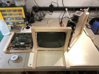
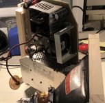
Not sure this is the proper forum, but I didn't know where else to put it. With my extra time amidst all of this pandemic stuff, I decided to build something that I have been thinking about for a while: a test stand that will let me test various components of compact Macs without tearing apart one of my machines every time to do it. The goal will allow me to have the analog board, logic board, floppy, and peripherals all easily accessible. It is small to be able to store it, and will allow the testing of compact CRTs as well. With the base CRT, I can test all but late-model Classic II analog boards. Currently, I am building the structure part, the photos are attached here. I will update you on how things are going. Most of the structure will be done by tomorrow.

The last thing that I need is to know what the Mouser part numbers are for the yoke deflector connector, both male and female. I am making extensions for all of the cables to allow me to lay out the parts easily. I suppose I also need an extra long internal floppy connector.

The first photo is the main structure: this is where the monitor will be mounted. You can see the mounting points (triangular pieces with holes in the corners).
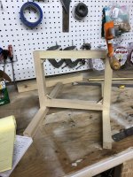
IMG_1264.jpg

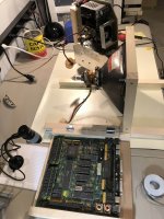
This is the small table that will hold the logic board:
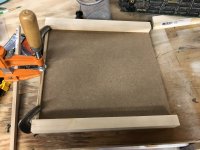
IMG_1266.jpg

Lastly, this is the frame that will hold the analog board up. This will all make a lot more sense once it is all together in one photo.
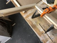
IMG_1267.jpg


LaPorta

Well-known member
It's really coming together now; I will probably be ready to test parts tomorrow.Here it is with screen installed, and logic board and analog board mocked up:

IMG_1268.jpg

Depending on just how long the anode cap is, the analog holder can swing in and out to be able to reach. The advantage of having it on the side is being able to adjust the trim pots without having to reach around the machine. It also folds in for storage.The logic board tray is also on hinges; it folds up and is secured to the main unit by a hook when not in use. I am going to make a separate floppy holder that I can hold a disk drive in so that I can test them after repair and lubrication.

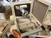
Next, you can see the side of the rear:

IMG_1269.jpg

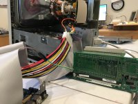
Tonight, I also got as far as running the grounding braid. The mount points with wing nuts will also hold wire leads with alligator clips to attach to the ground points on the analog board and the logic board grounding strip, respectively. You can also see the hook that holds up the logic board tray, in the stored position seen here.

IMG_1271.jpg


Juror22

Well-known member
This is a terrific project.I have a couple of cables to extend the power and HD, but I never thought of taking the concept this far - very cool!


Trash80toHP_Mini

NIGHT STALKER
Beautiful piece of work with some very creative problem solving solutions in that layout. Might I suggest adding a clear plexi shroud hinged to backside the A/B wing so the fan will properly cool its very hot components and the PSU? It would also protect and insulate the A/B's high voltage components from being being dirtied by fingerprints. [:)]  


adb9001

Active member
Fantastic!

Clever approach and just think of the time you will save.   

LaPorta Plug 'N Play  (tm)  

;-)

 
Last edited by a moderator:

pcamen

Well-known member
I like it.  For my SE/30 work, I got an extender power cable, used a couple of breadboard wires to extend the speaker cable, am using a longer SCSI cable, and an extended floppy cable that came with the FloppyEmu.  It allows me to have the MoBo on the desktop to the right, out in the open rather than having to futz to get it back in the case each time I do something. 

Similar concept I think but not as elegant as yours. 


LaPorta

Well-known member
Thanks everyone! pcamen, where did you mount your CRT? The floppy cable idea is genius! I have one of those as well, I guess I could use that. I was going to make my own. 
 

I am now waiting for my shipment of connectors, and I am going to make extension cables for everything else there is between the logic board, analog board, and CRT. These will include both 128k-Plus and SE series cables, so this can test any of them. The Classic will be a bit trickier but I think doable. From the spare boards I have, I’ll have a collection of spare but working boards so that I’ll have good ones to run whatever part I’m testing.

As for cooling, I figured the analog board is in the open so it should cool just fine, but what exactly was the suggestion about the plexiglass? Any other comments or suggestions? 


pcamen

Well-known member
where did you mount your CRT?
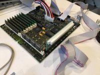
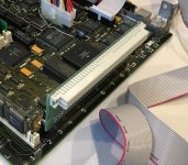
So, I literally just take the motherboard out of an SE/30 and then stand the rest of the unit up as is without the back. Then using an extension cable for the power, and for the speaker, I can put the motherboard on the desk next to the base unit with no back.  I don't have great pictures, but here is the gist from a couple of pictures I found.

IMG_8853.jpegIMG_8470.jpeg

This is what I used for the power supply:

https://www.amazon.com/Power-Supply-Motherboard-Extension-Cable/dp/B01MU18ZPN/ref=sr_1_3?dchild=1&keywords=20+Pin+Male+Female+ATX+Power+Supply+Extension+Cable+12+inch&qid=1585589758&sr=8-3

Screen Shot 2020-03-30 at 10.36.16 AM.png

It has more pins but you can just plug in as many as needed (being sure to line up both sides correctly) or cut it down.   And any basic male-female breadboard jumper wires work for the speaker extension cable.  Perhaps there is a perfect solution out there but I haven't found it yet.

https://www.amazon.com/EDGELEC-Breadboard-Optional-Assorted-Multicolored/dp/B07GD2BWPY/ref=sr_1_3?crid=272K4EDZL9KP4&dchild=1&keywords=breadboard+jumper+wires+male+to+female&qid=1585589844&sprefix=breadboard+male+femal%2Caps%2C207&sr=8-3

Screen Shot 2020-03-30 at 10.37.49 AM.png


pcamen

Well-known member
I should say, I didn't think up my setup, but borrowed the idea from another user here from another post. 


LaPorta

Well-known member
That's sort of what I had been doing previously as well. I have a PoS speaker from an SE that I took out years and years ago, so I just hook that up when needed. Otherwise, the 128k-Plus with them built in makes that not an issue. I like what you did for the power extension. I tracked down the actual parts on Mouser and built one. I am doing the same soon for the 128k-Plus.  Those breadboard wires are an incredible deal for that price! What is that small, electrical-taped wire in one of the photos?

I am hoping that after I make my "how to service floppy drives" video, I will have a good companion wooden stand for those as well.


Trash80toHP_Mini

NIGHT STALKER
As for cooling, I figured the analog board is in the open so it should cool just fine, but what exactly was the suggestion about the plexiglass? Any other comments or suggestions? 
For most of the AB open air cooling should be fine. What I worry about is the all important, unobtanium flyback, so my open air setup runs for only short periods. However I'm only playing with expansion cards.

Ffor troubleshooting and display calibration my guess would be that you're running the A/B  for much longer periods. It looks like your reversed A/B wing doesn't fold flush to the "box" when installed? Take an oblique shot of the just the A/B setup from both sides for more shallow angles than this one and I can knock together illustrations of what I suggested.

Oblique-AB-Stand.JPG

I really can't think of any functional improvements offhand, it's quite elegant. One question though: why are the front legs so long given the counterweight of the CRT? The only visual improvement (even a bit handier in use?) would be to cut them shorter and do the Jobsian chamfer thing while you're at it.  [;)]  

_____________________________________________________________________________________________________________________________________________________________

@pcamen What is and where did you get this fabulous PDS RA adapter?

Capture.JPG

More and detailed piccies please!

 
Last edited by a moderator:

LaPorta

Well-known member
No, it does not swing flush. It only goes flush for storage. It’s purposely angled so that you don’t have to reach around to adjust the controls for width, cutoff, etc. if the anode wires were long enough I’d just have it 90 degrees from the rest of the unit (alas, they are the not), so somewhere around 60 degrees is the best I can get.


Trash80toHP_Mini

NIGHT STALKER
No, it does not swing flush. It only goes flush for storage. It’s purposely angled so that you don’t have to reach around to adjust the controls for width, cutoff, etc. if the anode wires were long enough I’d just have it 90 degrees from the rest of the unit (alas, they are the not), so somewhere around 60 degrees is the best I can get.
That's exactly what I'd been referring to when I complimented you on creative problem solving. It's outside the box thinking, you've turned one side of the box topsy-turvey on the horizontal axis, most elegant! :approve:


Trash80toHP_Mini

NIGHT STALKER
@pcamen thanks for reminding me of that thread with the great pics! I've very casually been working on (much procrastination involved) a similar adapter card project for some time.

 
Top