• Updated 2023-07-12: Hello, Guest! Welcome back, and be sure to check out this follow-up post about our outage a week or so ago.

The Color Classic LCD Project.

pizzigri

Well-known member
ok, so I found something that worries me... essentially, in the PCC site (the only one that has info on the harness of the CC and related pinouts for the AB connector) here: https://powercc.org/takky/ there's a chart giving for pin 1 of the connector a -12V "input" (what does it mean... going out of the AB? going in from the LB? argh) in any case, this seems to be connected to a 7905, but wait! Later on, there's an image showing that you're supposed to get -10V from the onboard PS and solder a big bodge wire to supply those -10V to the connector (incidentally, pin 1), to be able to power up a 6200-6500 board.
So I have -5. -10 and -12v all on the same pin. First of all, in my replacement pcb I foolishly routed the -12v from the PSU at pin 1, following the chart, but I bet a 68K does not expect that voltage there so maybe that is the culprit. Second, there's no -5V rail (even at low amps) from the SFX PSU, so if it is confirmed that the LB needs -5v instead of -12V, I'll need to add a 7905 and reduce those -12 to -5v.
Why -5v? anybody knows?
All this will be confirmed tomorrow when I fire up the Analog board to check out all voltages.
BTW, remember everyone asking what does the BD11 connector is for? the one right next to the AB connector. Well it seems, since the ADB supply and power off (?) pins are also connected to it, like a convenient way to start the soft power when the board is out of the machine, i.e. for troubleshooting.
 

pizzigri

Well-known member
BTW. I really, really need a donor broken AB for the connector and hardware to go on with these experiments, anyone has one for me? and if I'm successful, I'll post all findings here so a LCD CC can be built using the info and gerbers I'll make available. BTW, I added the sense lines selection pads so that this could also be used for an original CC - provided a LCD capable of displaying 512x384 can be sourced.
 

pizzigri

Well-known member
Update... I fired up the old Analog board, and sure enough, pin 1 has -5V and not -12V. I imagine this could cause lots of grief to the LB.
Everything else meters as expected.
I cannot connect the old AB to the LB any more as I removed the connector...
Real 7905 ICs are not so common so I will have to add in a stupid LM337 regulator in the frigging PCB, meaning another 60+ euro for JLCPCB and another 10 days to receive everything. But, before that, I will bodge a regulator on the present pcb and see if it works.
 

pizzigri

Well-known member
So... progress, sorta.
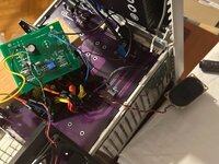
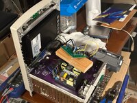
Still cant find out what's wrong, but at least something happens. I botched the -5v regulator so that now -5V are supplied to the LB. I made sure the LB still works as it chimes on the original CC. It does not want to soft start, it seems to start and it turns off immediately. But that could be my soft start circuit, which I shamelessly copied but maybe not well enough and it will be explored once it actually boots... in any case, I have plan B for the soft start and that is to use the classic SN74LS04 and two resistors.
Well, I jumpstarted the PSU, using green to GND, and the LCD fires up - all voltages are good, including 5VSB and the regulated -5V.
So I insert the CC LB, and switch it on. Argh! It starts screeching and then it becomes a pure tone, and obviously nothing happens. But the PSU is good, the LCD turns on ("no signal"), and the red light I misunderstood was coming from the PSU, is actually the red light from the Zuluscsi, starting up. I recorded the noise coming from the loudspeaker, any ideas?
 

Attachments

  • IMG_2176.jpeg
    IMG_2176.jpeg
    305.8 KB · Views: 17
  • IMG_2175.jpeg
    IMG_2175.jpeg
    365.6 KB · Views: 17

pizzigri

Well-known member
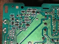
Additional information. I am looking at the original AB - there are two pins of the connector that go deep inside the board, pins 3 and 39. I tried following them, and found they both go, after a few components, to a block of the circuit that seems to be related to the 5/12V rails. I included the pics below. I measured the voltages at the various pins, and this is what I found. The AB is powering two HD.
12V rail: 11.511V;
5V rail: 4.993V;
Pin1: -5.051V (this is the pin that was labeled -12V on the Takky scheme, I realized it is also labeled LC630 so it's from the 630 harness).
Pin3: 4.951V
Pin39: 4.923V

So, pin 3 and 39 go here:
 

Attachments

  • IMG_2177.jpeg
    IMG_2177.jpeg
    518.3 KB · Views: 14

pizzigri

Well-known member
My understanding is that these two pins could be sorta “power good” sense lines? They go to the switching supplies and both produce 5v. This may have been simply disregarded by the Takky guys both because the AB works without feedback from the LB, and also because the 630 harness used all the way to the 5500/6500 does not provide any “power good” info, so maybe there was no point to remap these to a 630 harness?
Has anyone ever traced the connector of the 575/CC AB? I have seen in the past LCD modded CC, however they all used the original AB stripped of the EHT and CRT control circuitry.
 

pizzigri

Well-known member
@techknight and @Bolle you guys may have some insight on the above ? I promise everything I'll design will be posted here for every 68KMLA member to use if anyone wants to make a LCD version of their Mystic...
 

pizzigri

Well-known member
Tried connecting 5V to pins 39 and 3. I added a 440R current limiting resistor to each pin, just to be on the safe side. If it's a sense line (the voltages on both these pins do not seem to be regulated) the LB would have minimal draw anyhow. tested the PCB outside, connecting a 5V and 12V load and everything checks, all voltages good and stable as a rock. I didn't break out the Agilent 34410A but on my 4.5 digit handheld DMM even the last digit doesn't waver - even the little -12 to -5v converter checks. But the frigging LB does the same whining that screeches at first and then becomes a pure tone, as in the video!
Out of ideas, what can it be? What does compel a CC LB to do so?
Help!
 

pizzigri

Well-known member
Hi Techknight, I see... thank you for dropping by!
I have a scope, what do you suggest I do? Could there be some handshaking? pin 3, after a lot of routing, passes thru a couple active components (transistors) and ends up in the big CRT custom driver chip. Point is, since the board I am using to monitor the signals, has bot line transistor and FBT removed, I am unsure if the IC behaves normally. And what the hey does the CC LB need any info from the AB for? Up to the point of not booting. Unless, i am going at this the wrong way, and maybe should rather ask, what would make a 68K Mac cry out like that thru the loudspeaker?

If I manage to solve this, a drop-in replacement AB with LCD is possible and that could mean lots more life for many CCs, especially the Mystics.
 

MacKilRoy

Well-known member
This is a very cool project, and I hope you get it off the ground.

Wishing you lots of luck on it, I hope you succeed!
 
Top