• Updated 2023-07-12: Hello, Guest! Welcome back, and be sure to check out this follow-up post about our outage a week or so ago.

Calling it with SE/30 Simasimac Board

epalamaro

Member
So I had gotten this Simasimac SE/30 a while ago and tried to repair it. I posted about it on TinkerDifferent (https://tinkerdifferent.com/threads/simasimac-help-please.2842/#post-25938). I think I'm going to call this one unfixable, or at least not fixable by me. The SE/30, when shipped to me showed the typical pattern and had no chime. I then proceeded to recap it and got a happy Mac chime, but the same image on the screen. Having read a few things about SE/30 repairs before, I replaced UE8 with what I think is a suitable alternative (although a bit large for the area), but after doing so, I got crackling in the speaker and a black screen. I put the original one back... made no difference. I put another replacement on and I got a death chime. Only after leaving the screen on for about 20 minutes did the CRT jump back into life. Still had a simasimac pattern. I patched a few traces between the CPU and GLUE, GLUE and UB10 as well as UE 10 and a VIA as well as C6 capacitor and UB11. I'm not the best at soldering, so some of those broken traces/lifted pads were caused by me during the initial recap but some weren't. Anyway, since then, I've replaced all of UA8-UG8 and all of the F258s as well as UA9. Nothing. I then noticed that if I put pressure on one of the PAL sockets, that the screen would distort (video in the TinkerDifferent thread). I added some more solder to those pins as well as the 41264s... the screen never turned on again.

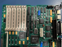
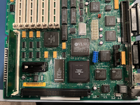
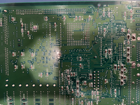
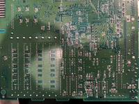
What's worse is that I just picked up a regular working SE to see if the analog board/power supply were to blame. After putting the SE/30 logic board in the SE case (with an extension), now the SE screen won't turn on even with the working SE board in it. So after that, I'd say these are going in a closet for a while. A shame because I've fixed so many other vintage computers in the past (M5126 Mac Portable, Color Classic, NeXT Cube, 128K). With this, it seems I'm over my head. I'll attach a picture of how the SE/30 board looks now... What do you all think?
 

Attachments

  • tempImagee4o8KT.png
    tempImagee4o8KT.png
    15.6 MB · Views: 38
  • tempImageZs59SA.png
    tempImageZs59SA.png
    15.5 MB · Views: 39
  • tempImageAM0JfK.png
    tempImageAM0JfK.png
    17.8 MB · Views: 32
  • tempImageJ4mvpP.png
    tempImageJ4mvpP.png
    17.4 MB · Views: 39

bigmessowires

Well-known member
That sounds super frustrating and I'm sorry to hear it hasn't worked out very well. I've never attempted a repair like this, but if it were my computer, I think I'd use a scope or logic analyzer to start examining some signals. Like is there any activity on the address and data bus? What do the signals going to the analog board look like? (the low-voltage signals on the logic board side, not the analog board itself) Also check continuity with a meter on all the pads and traces that you repaired, while poking and prodding at them gently.

If we are in "screen doesn't turn on" territory, then I think it should be fairly easy to find the initial problem. I don't have the pinout handy, but there are only about 10 wires going between the logic board and the analog board, and if memory serves they are power supplies, audio, vsync, hsync, and video data. Look at those last three on a scope and you'll learn something that may help.
 

Phipli

Well-known member
I think I'd use a scope or logic analyzer to start examining some signals.
The first thing is usually a visual inspection - you have to look systematically and very close, but it finds a lot of issues.

The other things are that scopes are very expensive. Despite doing some electronics design and a lot of repair for my dad and I, I've never been able to justify the cost of a scope good enough to be useful.

I do have a multimeter, a little cheap Logic Analyser (which I rarely use) and a frequency counter (which I use a lot). Combined, these are about $30, and easier to justify when you don't regularly need to capture analogue signals. Another thing worth getting is a cheap component tester ($15ish) (allows you to only need to replace bad caps and saves a fortune in parts, as well as checking for bad transistors and other things).

The one slightly more expensive thing I'd suggest : a TL866 (about $65 these days?) - as well as programming EPROMs and MCUs, they can also test some logic chips and RAM chips, which is a huge help when you suspect a chip.
 

bigmessowires

Well-known member
Yes fancy scopes can certainly be expensive. Depending on your location, there may be perfectly good analog scopes going begging for almost free, though. I see dozens of them at every swap meet here. The downside is they're huge and bulky. Something like a DSO Nano is another option, they're under $100 but don't have the highest bandwidth. A simple 8-channel 24 MHz logic analyzer can be had for under $10 and is an indispensable tool. I use mine absolutely constantly and couldn't imagine ever doing circuit troubleshooting without one. It would be like fixing software bugs without access to a debugger, just staring at the code and hoping the solution will leap out.
 

Phipli

Well-known member
Something like a DSO Nano is another option, they're under $100 but don't have the highest bandwidth
They're only any good for 8bit era machines sadly. Same for a lot of the cheap analogue scopes.

A lot of people doing retro Mac repairs only really have an iron and a multimeter, but you'd be amazed what you can find by a mix of symptom analysis, looking, continuity testing and voltage measurement.
I use mine absolutely constantly and couldn't imagine ever doing circuit troubleshooting without one.
Don't forget the cumulative knowledge you're bringing to the table too. Most of us wouldn't know what to do with the data they captured beyond whether the bus was active or not.

I'm very used to doing repairs with minimal tools. I do wish I had a good scope though :)
 

epalamaro

Member
Thank you both for the replies and the suggestions! Yeah I only have a multimeter and a soldering station at the moment, definitely looking to acquire more useful tools in the near future. I'll look for that pinout you mentioned. Need to get a Mac from this era working so I can use my Floppy Emu to its full potential ;)
 

bigmessowires

Well-known member
After putting the SE/30 logic board in the SE case (with an extension), now the SE screen won't turn on even with the working SE board in it.
After re-reading this, it sounds like you're thinking that the SE/30 logic board somehow killed the SE's analog board or CRT?
 

Chopsticks

Well-known member
could be a bad PAL, but im more inclined to think after re-soldering the pins, its broken a pcb trace or via etc.
i would go over the video circuitry both with continuity and resistance too. rule that out sorta thing.

you likely have to separate faults going on with both the se/30 and the SE analog board.

since you have SE that was working prior its likely that something failed on the analog board at the same time you tried using the SE/30 logic board with it.

i'd focus first on getting that se working again and afterwards when you're in mood for it to tackle the se/30.
or jsut get a new SE/30 PCB and use your old se/30 as a donor board


also its hard to tell from the photos but it almost looks like the positive lead of C2 is shorting to a via/pad on the back of the board between C83 and R15. again hard to tell from the photo so it may not be anything
 

tt

Well-known member
I read some wisdom here that the cable harness between the analog board and the logic board can become flaky with age. I had a machine that wouldn't consistently turn on (mostly wouldn't) and swapped the harness out and it seems to be fine now.
 

cheesestraws

Well-known member
Most of us wouldn't know what to do with the data they captured beyond whether the bus was active or not.

To be fair 'are there wiggles here and are they approximately the right shape and the right voltage' is an incredibly useful thing to know.
 

AstroFirebird

Active member
I just fixed a similar issue with the simasimac and happy chime. UJ6 ended up being the culprit, but you definitely have a problem in the video circuit. It's hard to tell what's exactly going on without a logic probe or oscilloscope. Check the continuity between the address lines and UJ6 then from pin 8 of UJ6 to pin 4 of UE7. If those test good, make sure there's continuity between all of the PAL chips. In the video on the other forum, it looks like you're pushing on UE7 which I believe is mainly responsible for initializing the VRAM. The simasimac screen is essentially just the standard state of the VRAM, so something dealing with UE7 would make a lot of sense. If you want to end up shot gunning PAL chips I ended up using GAL16V8D-15LP chips and programmed using TL866. Boelle was nice enough to recreate the code for them and you can find it in the reloaded board files.

Verify the components you resoldered and make sure you didn't bridge any connections. Did you verify the SE Analog board/CRT was even good before plugging the SE/30 board in?
 

Phipli

Well-known member
Have you checked the voltages? 5v is the 5th pin from the top left of the floppy port. Thats' the important one, and video is often the first thing to stop working with low voltage.
 

epalamaro

Member
@bigmessowires Yeah that's what I was initially thinking. Although I left it on for a while with the regular SE board in it, and the screen came back on. I feel like the SE/30 board is shorting out something, although I am speaking with basically no knowledge and don't know if that's even a possibility haha. Thanks to everyone for the help! I'll start checking and report back...
 

epalamaro

Member
@AstroFirebird Yeah I had actually read through the thread you posted. Glad you were able to give yours some more life! So I just tried pin 8 of UJ6 to 4 of UE7. No usual beep that would signify continuity, just 527 on the screen. Have to look up what that means as I'm basically just learning as I go along. I will probably pick up one of those TL866s as a few people have suggested that now. Its really awesome that knowledgeable people are recreating proprietary parts..
 

epalamaro

Member
@Chopsticks That lead wasn't actually making contact with anything; it is raised off of the board slightly. Good eye though! Yeah I think going over the video circuitry is the logical next step.. will report back..
 

AstroFirebird

Active member
@AstroFirebird Yeah I had actually read through the thread you posted. Glad you were able to give yours some more life! So I just tried pin 8 of UJ6 to 4 of UE7. No usual beep that would signify continuity, just 527 on the screen. Have to look up what that means as I'm basically just learning as I go along. I will probably pick up one of those TL866s as a few people have suggested that now. Its really awesome that knowledgeable people are recreating proprietary parts..
It's 527 ohms? That's definitely a problem if the resistance is truly that high. I'd verify pin 8 of UJ6 has a good connection and then verify pin 4 of UE7 is good as well from underneath. If they look good, remove UE7 from the socket and inspect the IC itself along with the socket. if everything ends up looking good, I'd try running a wire between those two pins and seeing what it does.
 

epalamaro

Member
Although one thing (actually many things) that doesn't have continuity is pin 1 of UE7 to all of its endpoints. I tried adding a little solder, nothing. I'll try to wire them up and see what happens
 
Top