• Updated 2023-07-12: Hello, Guest! Welcome back, and be sure to check out this follow-up post about our outage a week or so ago.

Blueberry iMac G3 - No signs of life

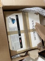
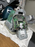
My aunt recently asked how to get rid of her old blueberry iMac and I said ship it to me! It showed up in the original box with all the accessories, except it won't power on. No clicks, no bongs, nothing. No signs of life. I found a PDF of the service manual and when through the trouble shooting tips. I find 5V power at the test points on the mother board, tried reseating the CPU card, reseating the system RAM and the video ram, new battery, and Cuda reset. I even found a new old stock PSU on eBay. That one showed up and the largest black capacitor on it is bulging on the top. (flashbacks to the iBook g4 and the capacitor plague of the mid 2000s.

Tried the new power supply and got the same results. The new supply does make a slight (very very slight) whine noise when plugged in. The seller accepts returns so I'm thinking of sending it back and getting back $55.

I'm at a loss as to what to check next. My electrical meter is too cheap to properly test the caps on the PSU, but I've recapped a TiVo's power supply before, so I'm familiar with the process. Is there another step I should check before hand?

Specs: M7345LL/A - 266mhz, 32MB Ram, 6mb video ram, 10/100 network Blueberry

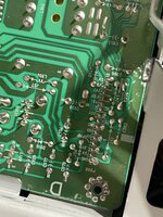
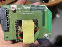
Original Power Supply
IMG_8883.jpeg

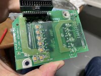
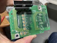
NOS Power Supply (notice that nice round top)
IMG_8884.jpeg
 

Attachments

  • IMG_7780.jpeg
    IMG_7780.jpeg
    2.2 MB · Views: 29

3lectr1cPPC

Well-known member
the typical revival method on the slot-load models is to leave them plugged in for a few days - usually gets them going. Worth a try but yours is a tray load. That bulging cap will have to be replaced, it's a good place to start.
 
the typical revival method on the slot-load models is to leave them plugged in for a few days - usually gets them going. Worth a try but yours is a tray load. That bulging cap will have to be replaced, it's a good place to start.
I'll just put the original power board back in, none of those are bulging. I did read about that method. I just put the original board back into the chassis and plugged it all in.

Another thing I noticed is that there are labeled points for 130v and 75v. Neither of those (on either board) read full power. Both read at about 50%, or would they only read correctly when powered on?

Also, is running the compute like this ok for bench testing?
 

Attachments

  • IMG_8897.jpeg
    IMG_8897.jpeg
    2 MB · Views: 30
  • IMG_8898.jpeg
    IMG_8898.jpeg
    1.6 MB · Views: 27

3lectr1cPPC

Well-known member
Not great to have everything exposed like that in terms of safety, just don't touch anything to be safe about it and you should be fine. The voltage issue implies a PSU or analog board issue.
 
Not great to have everything exposed like that in terms of safety, just don't touch anything to be safe about it and you should be fine. The voltage issue implies a PSU or analog board issue.
It's in the basement on a work table. So its way from small hands and I'll be extra careful.

The analog board is the one that drives the CRT, right? Are there troubleshooting steps for those or just make a shopping list of capacitors and hope for the best? I'll leave the computer plugged in for a few days to see if it wakes up.
 

3lectr1cPPC

Well-known member
There are troubleshooting steps - but I don't know them. Someone with more experience in that field should hopefully chime in.
 
Hey All,

Got the new PSU from eBay. It was NOS, but the largest capacitor was bulging and basically gave me the same readings as my original power supply board.

Tried leaving the unit plugged in for the past few days. Not change.

Luckily I can return the eBay PSU and get my money back.

Next step is a recap. Is it safe to assume that I should recap both the power supply and analog control board?
iMac Power Supply Part number (P/N 6870T139D11
I think I found a short on the board at around B4 (R906) or is that something else? This board looks to be glue in (is that hot glue?)
IMG_8931.jpeg

Should I also remove this vertical board and replace the caps on the brown board?
IMG_8936.jpeg

IMG_8935.jpeg

IMG_8937.jpeg
 
Before digging into re-capping. Thought I would follow this block diagram and took off the power filter. There is some sort of white residue on it. Something leak?
Screenshot 2023-03-30 at 8.53.02 PM.png
 

Attachments

  • IMG_8950.jpeg
    IMG_8950.jpeg
    3.1 MB · Views: 22
  • IMG_8952.jpeg
    IMG_8952.jpeg
    2.6 MB · Views: 23
  • IMG_8951.jpeg
    IMG_8951.jpeg
    3 MB · Views: 25
I think this is a complete capacitor list for the main board of the PSU.

bondi-caps02.jpg

IndexQuantityPart NumberManufacturer Part NumberDescriptionCustomer ReferenceAvailableBackorderUnit PriceExtended Price USD
11P5901-NDEEU-EB2C330CAP ALUM 33UF 20% 160V RADIALB100.860000.86
21P13622-NDEEU-EE2C101CAP ALUM 100UF 20% 160V RADIALC101.670001.67
31P5131-NDECA-1AM682CAP ALUM 6800UF 20% 10V RADIALF101.390001.39
45493-1754-NDUPW1A332MHDCAP ALUM 3300UF 20% 10V RADIALG501.340006.70
51P124270-NDEEU-FK1A682SCAP ALUM 6800UF 20% 10V RAD THH103.220003.22
61P10284-NDEEU-FC1E222CAP ALUM 2200UF 20% 25V RADIALI101.790001.79
71B43644A9687M000-NDB43644A9687M000CAP ALUM 680UF 20% 400V SNAPJ1013.1800013.18
82P5544-NDECA-1EHG102CAP ALUM 1000UF 20% 25V RADIALA201.060002.12
91P124237-NDEEU-FR2A101CAP ALUM 100UF 20% 100V RAD THD101.290001.29
101P13119-NDEEU-EB1C102CAP ALUM 1000UF 20% 16V RADIALE100.900000.90
112P1167-NDECE-A1CN101UCAP ALUM 100UF 20% 16V RADIALK200.750001.50
121P1180-NDECE-A1EN101UCAP ALUM 100UF 20% 25V RADIALL100.880000.88
131P5182-NDECA-1HM101CAP ALUM 100UF 20% 50V RADIALM100.470000.47
142P5181-NDECA-1HM470CAP ALUM 47UF 20% 50V RADIALN200.350000.70
1511189-4015-ND50ML1MEFC4X5CAP ALUM 1UF 20% 50V RADIALO100.270000.27
161P825-NDECE-A1HKA2R2CAP ALUM 2.2UF 20% 50V RADIALP100.330000.33
171P5149-NDECA-1EM220CAP ALUM 22UF 20% 25V RADIALQ100.280000.28
181P10275-NDEEU-FC1E471CAP ALUM 470UF 20% 25V RADIALR100.780000.78
 

3lectr1cPPC

Well-known member
Great set of info here. This is for a rev C right? Mind if I add the image and specifications to my website so that other people can find it easier in the future? I’ll credit you on the page of course.
Edit: actually don’t really understand all about what the letters mean, and the hexagons.
 
Great set of info here. This is for a rev C right? Mind if I add the image and specifications to my website so that other people can find it easier in the future? I’ll credit you on the page of course.
Edit: actually don’t really understand all about what the letters mean, and the hexagons.
I took the image from another thread. The list of values was not my work but I confirmed it matched my board. The hexagons were values that were not listed on the graphic its self. The hexagons were effectively my "to do" list of values to look up. I did that and added each to my cart on digikey. On digikey there is a "customer reference number" where I put in the letters to match up to the labels on the graphic.
 
Here are the caps on the brown board. Not sure what it does.

Also, I'm a bit out my league on this capacitor stuff. I matched each value on digit-key based, selected Panasonic when I could, and match approximate physical size. Things like ripple I wasn't sure about.
 

Attachments

  • IMG_8956.jpeg
    IMG_8956.jpeg
    1.8 MB · Views: 18

CC_333

Well-known member
I have several iMac G3s, including two or three tray loaders, that will probably need this done sooner or later, which I'm dreading.

However, the last time I tried them, they all still worked the last time I powered any of them on ~8 years ago, so hopefully nothing went bad in the meantime, including batteries (I'm pretty sure I took all those out, but not 100% sure. It would be very dreadful to find out they've all been battery bombed!)

c
 

Daniël

Well-known member
I would suggest looking at this thread, OP has already documented the caps for the Trayloaders:


Do note that the flybacks on these also tend to fry themselves. There do exist third party replacements, like the HR46176 from HR Diemen.
I've yet to work on my Trayloaders, and am still on the hunt for the Strawberry to at least have all the different colors of plastics to be able to complete a fully restored Yum + Bondi set, but I stocked up on six of these just to ensure I've got them before they might not be available any longer.
 

AwkwardPotato

Well-known member
That one showed up and the largest black capacitor on it is bulging on the top.
The 400V rated capacitor after the bridge rectifier often appears to be bulging, and it is in fact normal. It's a plastic disc on the top that gives the capacitor that appearance; it does not need to be replaced.
Another thing I noticed is that there are labeled points for 130v and 75v. Neither of those (on either board) read full power. Both read at about 50%, or would they only read correctly when powered on?
This also seems to be normal, both supplies read about half the nominal voltage on my tray-loader when it's shut down.
Next step is a recap. Is it safe to assume that I should recap both the power supply and analog control board?
No! It is HIGHLY unlikely that the fault lies in the caps, at least for a system of this particular age (and speaking from experience working on my tray-loader and a Studio Display of the same vintage: these LG-made monitors seem to be on the cheaper side of the spectrum and tracks can lift off the boards easily; shotgun-swapping large swaths of components runs the risk of introducing new problems faster than you can fix the old ones).
I think this is a complete capacitor list for the main board of the PSU.
Haven't gone through the list thoroughly but the parts in the Digikey order may not all be suitable. For instance the 3300uF caps were originally low-ESR types from the factory, but the 3300uF cap listed in the order is a general purpose part, NOT a low-ESR one. In a system with power requirements like those of the iMac, it is fairly important that the proper low-ESR parts are used where necessary.


The first step I'd take in troubleshooting would be to unplug the power cable from the power filter board, and jumper the purple wire to the brown wire (I'd use a 470-1000ohm resistor to be safe, but you can probably just stick a piece of wire in the connector) to force the power supply to turn on. If the fan in the iMac starts spinning and the power light comes on amber, your problem is with the logic board. If the system is still lifeless, the fault can be narrowed down to either the power supply or analog board (although not the kind of fault associated with the flyback transformer).

If the problem ends up being with the PSU/analog board, start by reflowing the solder joints on all the connectors and large components on both boards (every power-up problem with my tray-loader has been solder joint related).
 
The 400V rated capacitor after the bridge rectifier often appears to be bulging, and it is in fact normal. It's a plastic disc on the top that gives the capacitor that appearance; it does not need to be replaced.

This also seems to be normal, both supplies read about half the nominal voltage on my tray-loader when it's shut down.

No! It is HIGHLY unlikely that the fault lies in the caps, at least for a system of this particular age (and speaking from experience working on my tray-loader and a Studio Display of the same vintage: these LG-made monitors seem to be on the cheaper side of the spectrum and tracks can lift off the boards easily; shotgun-swapping large swaths of components runs the risk of introducing new problems faster than you can fix the old ones).

Haven't gone through the list thoroughly but the parts in the Digikey order may not all be suitable. For instance the 3300uF caps were originally low-ESR types from the factory, but the 3300uF cap listed in the order is a general purpose part, NOT a low-ESR one. In a system with power requirements like those of the iMac, it is fairly important that the proper low-ESR parts are used where necessary.


The first step I'd take in troubleshooting would be to unplug the power cable from the power filter board, and jumper the purple wire to the brown wire (I'd use a 470-1000ohm resistor to be safe, but you can probably just stick a piece of wire in the connector) to force the power supply to turn on. If the fan in the iMac starts spinning and the power light comes on amber, your problem is with the logic board. If the system is still lifeless, the fault can be narrowed down to either the power supply or analog board (although not the kind of fault associated with the flyback transformer).

If the problem ends up being with the PSU/analog board, start by reflowing the solder joints on all the connectors and large components on both boards (every power-up problem with my tray-loader has been solder joint related).
So apparently forum notifications were turned off and didn't see this response. I replaced about 5 capacitors so far. The ones below that have an orange circle over them.

Regarding the other troubleshooting steps. I did confirm that the power switch works with a multimeter. That should be the same as the shorting the connector. Nothing happens when this happens.

I can always put the old caps back on the board, but first I can re-flow. Would that just mean to heat each of the solder points with my solder gun until it melts, then let it cool?
 

Attachments

  • bondi-caps02.jpg
    bondi-caps02.jpg
    937.6 KB · Views: 8

AwkwardPotato

Well-known member
Would that just mean to heat each of the solder points with my solder gun until it melts, then let it cool?
That’s the gist of it, although it’s a good idea to add a little bit of fresh solder to the joint as well to guarantee that it’s solid.
Regarding the other troubleshooting steps. I did confirm that the power switch works with a multimeter. That should be the same as the shorting the connector. Nothing happens when this happens.
It is good that the power switch can be ruled out, but pressing the power switch is not the same as shorting out the connector. The exact details are a little fuzzy for me since it’s been a few months now, but the line in question on the power connector (PFW, which turns on the power supply) is controlled by the CUDA chip on the motherboard, which is also responsible for detecting when the power switch is pressed. Jumpering that line as mentioned earlier ought to determine whether or not the motherboard is at fault. If that circuit on the motherboard isn’t operating properly, your easiest option may be to find a new motherboard; they are still relatively easy to get. Perhaps try reflowing joints on the connectors on the power filter board just to rule that out too.

If the system is still lifeless with the power connector jumpered: as I recall, the PFW signal comes from the CUDA, and snakes its way through the power filter board and cables up to the power supply board. It then goes through a different cable over to the analog board, where it’s used as an input to the microcontroller that handles the built-in monitor. The microcontroller then generates its own PFW output, which goes back over to the power supply board, through an optocoupler based circuit, and starts the power supply controller ICs.

In other words, if there’s a bad solder joint related to the PFW signal anywhere after the power filter, or the microcontroller on the analog board isn’t functioning properly, I imagine it would cause what you’re seeing right now. You can probably rule out the power supply since you’ve already tried another one.
 
Top