Apple III shows garbage on screen on startup

wottle

Well-known member
I just picked up an Apple III locally and it came with a ProFile 5MB Drive (unfortunately no Profile card in the machine), two Apple /// Monitors, and the external floppy drive. I need to replace the RIFA caps as the big ones are cracked significantly.

IMG_3008.jpeg


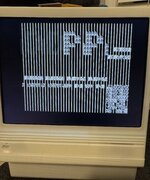
However, I decided to start it up in the garage to get an idea of if it could boot. I know nothing about the III, other than that they were short lived and had thermal issues. When I started it up, the good news is I do get a picture out and the display on the /// Monitor looks pretty good. (The other /// Monitor has a tear in the anti-glare screen, so I need to disassemble it and remove. the screen). Unfortunately, the screen displays two screens of gibberish.

First, this, with a square in the bottom right that is changing:
First Boot Screen.gif


Then I get a second screen that looks like this:
Second Boot Screen.gif


The screen goes black and then it repeats. I didn't let it go too long, because the RIFA caps looked like this (Yes, it appears there is a hole in one of them):
IMG_3021.jpeg


IMG_3017.jpeg


The remind me of the Apple II when it has memory chip issues. So, I decided to remove the RAM card, give everything a nice wipe down, remove every RAM chip, spray some DeOxit on the sockets, and reinsert them in a different order. I also removed and put DeOxit on the CPU socket. Unfortunately, the same result.

While I wait for my caps for the PSU, any thoughts on where I can start troubleshooting / ordering some replacement chips. Is it possible the CPU is bad? Is the 6502 available to buy if it was?

Also a quick update that may give some more idea of what's happening: when I do a Open Apple-Control-Reset, the screen resets and it appears the floppy doesn't try to reload, but the interesting thing is when I start typing on the keyboard, I do see the pattern change, which makes me believe some boot up is happening, but maybe the video circuit is bad. Not sure if that helps, but any advice would be appreciated!
 

wottle

Well-known member
I went through the task of removing, cleaning the legs, applying DeOxit to the sockets, and re-installing every socket chip on the board, and unfortunately the end result is the same. I'm also beginning to think the video output is scrambled, but the machine may actually be booting and the weird pattern in the lower right corner is actually the RAM test that should be displayed in the upper right.

I decided to fully disassemble the power supply and remove the RIFAs. Upon doing so, the 0.22uF one ended up looking worse than I originally thought, and when I tried to test it with my multimeter, it showed nothing, so I suspect it already blew. I'm wondering if that may be part of the problem - the RIFA is bad and is somehow affecting the PSU's ability to produce the right voltages. I always thought the RIFAs were basically there to filter out noise on the incoming power, so that doesn't seem like it would affect other things. Anyway, I have a set of caps from Joe's Computer Museum and will give it another go when the PSU is in better shape.
 

stepleton

Well-known member
It's good to change out old RIFAs, but they don't cause this kind of problem you see on the screen. RIFAs sit on the input ("primary") side of the power supply and help the computer be a good citizen on the power grid. A power supply has two sides, usually: the side that takes in the AC mains ("primary") and the side that makes DC power for the computer ("secondary"). RIFAs keep the buzzy electrical noise that the computer makes from going out into the electrical grid and interfering with other electronics. If they break, then perhaps that doesn't work so well, but nothing on the secondary side (like the whole computer-y part of the computer) is liable to care very much.

It's a good idea to check power first when diagnosing a problem. But the main thing to check is whether voltages are right (is the +5V rail at +5V? +12V at +12V? and so on). If they're off, you can get all sorts of wacky problems. It's also good to check voltages at several spots in the computer: find some chips here and there, search online to find out which pins get +5V and GND (or whatever), and measure those voltages. If things are pretty close to the correct voltage everywhere, you can feel more confident that power is OK.

The last power thing that people like to check is "ripple": is the power supply emitting a stable +5V (or whatever) or is it jumping around or oscillating? This is harder to measure without an oscilloscope, but if you can't measure it, I wouldn't worry about it too much.

...

If your power supply is making good voltage, then you probably have a bad chip somewhere in the system. Your journey of digital hardware troubleshooting now begins. You will need to build an understanding of what the logic circuits in the computer do (e.g. by looking at schematics), and start making theories for how they could generate the behaviour you see when they break. Then you take measurements that either confirm those theories or that show that they were false. You repeat this until you have the correct theory, the one that says that one particular chip (hopefully just one!) is broken. Replace that chip and hopefully you will find that you were right!

This kind of diagnosis and troubleshooting is a skill that takes time to develop. It also helps to have good measurement equipment, like an oscilloscope or even a logic analyser (but get a scope first if you can only get one). Once you've got it, though, fixing electronics in this way is a really fun and rewarding puzzle game, a great deductive logic exercise. It can also be social, because you can trade theories with other people online who have also wrestled with the same computer or with similar computers.

If you'd like an example of this kind of skill at work, I recommend watching some of the videos on the Adrian's Digital Basement YouTube channel. Not the ones where he fixes CRTs; that's not digital logic. Look at the ones where he's fixing computers, like the recent set of SE/30s. There are many others. You can see him apply this kind of reasoning and use the same kinds of tools that most diagnosticians would use to solve problems like the ones you're seeing.

...

In your posts so far, you have already formed a theory: it says that the computer is working but the display is broken. Find a way now to test this theory. If I were you, I'd see if I could get the computer to a BASIC prompt, which I think on the Apple /// requires a boot disk. If you can get to a prompt, can you do something that makes the computer beep? Or is there some other program or some other way where in normal operation the computer can beep? Or it can share some other clue that it's working normally without using the display to do that?

If I could achieve this, then I would conclude that the problem is localised to the display system and continue troubleshooting there. This would be a major step because it would eliminate loads of possibilities and shorten the list of suspect chips from dozens to perhaps 10-20? (I don't know much about the ///!)

Good luck!
 

wottle

Well-known member
Appreciate the post. Yeah, unfortunately I got into computers with a Mac SE, so the Apple II is pretty foreign to me and the Apple III is even more of an odd beast. So I'm hoping to try to get it to boot something useful that might be able to confirm that it actually is booting. I have PCBs and parts on order to make an adapter to allow me to plug in my FloppyEmu into it internally for it to serve as the boot drive. Hopefully at that time I will have the PSU recapped and will be able to test the voltages.

I found the schematics for the video circuitry and so while I wait for parts, I will likely go over those chips and ensure their traces are all good. Gotta fill my time somehow!
 

Arbee

Well-known member
On the pre-recall machines the problems weren't thermal per se, they were cheap tin contacts on the connector between the motherboard and the RAM array. (The recall changed them to higher-quality connectors, but that's a lot less sexy of a story than "Steve Jobs hated fans so the computer failed!"). Either way I'd suggest cleaning that connector with DeOxit or something.
 

wottle

Well-known member
Yeah, that RAM board was a bear to get off. I will try to hit it with some DeOxit.

Another update with some troubleshooting progress: I did confirm the III is booting. I was able to make an ADTPro SOS disk from my Apple IIc+ and booted the Apple III with it in the drive. And, I certainly can tell it is booting SOS and launching ADTPro!

tempImageMk5HCh.jpg

So, even though the video output is gibberish, I can interact with the app with the arrows and it is beeping at me, so I'm encouraged by that. I'm hoping it is a bad video ROM, but that's pure speculation at this point. But it gives me hope that there's not something horribly wrong with this machine. When I get my order from Joes Computer Museum (PSU recap kit and video ROM), I'll swap it out and see if things improve!
 

Arbee

Well-known member
The /// doesn't have a video ROM. Text mode characters are fully programmable, like the C64 and some other machines.
 

stepleton

Well-known member
That's good news about the system booting!

Here's a trick you might be able to try now. The ///'s video RAM occupies two chips: 2114 SRAMs that together offer a kilobyte of memory. Are they in sockets? Try swapping them and seeing if the display changes. If the problem moves along with the chips, it increases the likelihood (but does not guarantee) that the problem is in the chips.
 

wottle

Well-known member
That's good news about the system booting!

Here's a trick you might be able to try now. The ///'s video RAM occupies two chips: 2114 SRAMs that together offer a kilobyte of memory. Are they in sockets? Try swapping them and seeing if the display changes. If the problem moves along with the chips, it increases the likelihood (but does not guarantee) that the problem is in the chips.
Swapped the chips and the video output is exactly the same. I'll probably use the schematics to trace connections to and from those chips, along with what I thought was the Video ROM. Appreciate all the tips, everyone!
 

stepleton

Well-known member
Is there a difference between a video ROM and a video control ROM?
Looks like this chip is shown on the left side of the schematic here:

When people say "video ROM" for 8-bit Apple-y machines, they are probably thinking of something like a character ROM: memory that stores the bitmap "font" data for letters shown on the screen.

This "video control ROM" is different: it's used to generate control signals for the video system. Rather than use a collection of logic gates to transform a set of digital inputs to digital outputs, the Apple /// designers have reduced the parts count by simply storing that transformation in a ROM. This is not an uncommon trick for the time, I don't think; you also find it in the Apple Lisa's "video state ROM". It's a bit like someone using a big 100x100 table to add two numbers between 1 and 100 instead of doing the sum algorithmically (i.e. with a pencil and paper).

I don't know what the signals coming out of the ROM do (shown on the left side of the schematic diagram for the chip), but they seem to have names like AHIRES, BHIRES, AIILORES, and more. Close study of the schematic would tell the tale along with the contents of the ROM itself.

I could not say without that study whether problems with this ROM could cause the trouble you're seeing.
 

stepleton

Well-known member
A tangent:
It's a bit like someone using a big 100x100 table to add two numbers between 1 and 100 instead of doing the sum algorithmically (i.e. with a pencil and paper).
This example isn't as contrived as you might think... The first-gen IBM 1620 computer didn't have arithmetic hardware: it kept tables for addition, subtraction, and multiplication in RAM (not ROM). The IBM development code name for the computer was "CADET", which people joked stood for "can't add, doesn't even try."
 

wottle

Well-known member
Looks like this chip is shown on the left side of the schematic here:

When people say "video ROM" for 8-bit Apple-y machines, they are probably thinking of something like a character ROM: memory that stores the bitmap "font" data for letters shown on the screen.

This "video control ROM" is different: it's used to generate control signals for the video system. Rather than use a collection of logic gates to transform a set of digital inputs to digital outputs, the Apple /// designers have reduced the parts count by simply storing that transformation in a ROM. This is not an uncommon trick for the time, I don't think; you also find it in the Apple Lisa's "video state ROM". It's a bit like someone using a big 100x100 table to add two numbers between 1 and 100 instead of doing the sum algorithmically (i.e. with a pencil and paper).

I don't know what the signals coming out of the ROM do (shown on the left side of the schematic diagram for the chip), but they seem to have names like AHIRES, BHIRES, AIILORES, and more. Close study of the schematic would tell the tale along with the contents of the ROM itself.

I could not say without that study whether problems with this ROM could cause the trouble you're seeing.
Interesting. I was thinking it was like the character ROM and the distorted symbols was a sign of that. But it wouldn't have explained the fact that the characters were in the wrong place on the screen. I'm hoping maybe something in the functionality of that video control ROM might be the culprit. Given it was $10 to add to my order with JCM, I figure it would be worth it to swap it out and try. In the meantime, I will be checking the traces to make sure it's not a broken trace somewhere. The board is in immaculate shape, so I don't believe it is, but it won't hurt to check the direct connections from it.
 

stepleton

Well-known member
Do you have an oscilloscope? I would give some serious thought to getting your hands on one. Maybe a friend has one you could borrow? There are some relatively cheap options out there now.

I naively give that ROM a 50% chance of fixing the issue. We know that the corruption is affected by the row and column that the machine is drawing to the screen, and I don't quite see right now how the ROM behaves differently for different rows and columns visible on the screen. It's possible that they do and I'm missing it, though.

Chapter 6 of this document explains the Apple /// video system in some detail:
It starts on PDF page 99. I would give it a close look and see if anything in the text or diagrams reminds you of the trouble you're seeing. You don't have to understand everything 100%, just start building an intuition for what the parts might do and how they connect to each other. And if you see a chip or component named (e.g. LS374, which is short for 74LS374), Google the part number and check out its datasheet, getting some insight into what that part is for.

This study can inspire you to come up with hypotheses about the problem and ways you can test if those hypotheses are correct.
 

wottle

Well-known member
Sadly, no oscilloscope or any knowledge of how they work. I might need to do some more studying on some of the YouTubers to get an idea of what things to check for.

I did check the traces from the video control ROM and they all checked out (except the two I could not find the destination for in the schematics. One was on readable and the other (PG2) I could not find on any of the other pages of the schematic. I'm going to hold off on doing too much more until I can get the PSU recapped and also just give the video control ROM a shot.

Really appreciate all the helpful advice here. I'm hoping to get this machine back to its original glory! Given that it looks like I have one of the earlier versions that did not have the extra ventilation holes, does anyone have thoughts on adding a case fan to help keep the temperatures down? I found a few references to people attempting to add fans, but none with details. (Edit: never mind, found this: https://68kmla.org/bb/index.php?thr...talling-a-fan-into-an-apple.43368/post-472788)
 

wottle

Well-known member
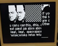
Playing around with it a bit more to see if I can get a better understanding of the issue(s). Looks like it's more than just the characters being messed up. I ran the Diagnostics disk and hit enter on the first option (run all tests?). I get this screen:

IMG_3091.jpeg

So it looks like the pucture is also being drawn incorrectly for non-text as well. It seems to have things drawn in the wrong place on the screen and is repeating some of the information (I believe this is trying to say something to the effect of "If you can see this clearly, press space. Otherwise, press return"). I have tried replacing a few of the chips in the video circuitry schematic that I could find elsewhere, but without an oscilloscope and the knowledge to use it, I'm really just swapping components at this point. Hopefully I will find the issue and this can help someone else who might experience something similar. Still not sure if my Video Controller ROM has shipped yet, but I'm still hopeful that that ROM controls how the output is produced and could explain this behavior.
 

stepleton

Well-known member
Shifted and repeated video suggests address bits to me. The fact that it's in large chunks suggests high-order address bits (more like A7 or A8 than A1 or A2 or whatever). At this point I'd look at schematics/read the theory of operation document and try to imagine what kind of failure could cause this kind of video distortion, and I'd be inclined to focus on how addressing works for the video system as I go.

You've already measured the traces on the board, so that reduces (but doesn't eliminate) the chance of a connectivity issue: did you check all the way up the component legs or lower down on the solder joints?

If the diagnostics disk doesn't actually contain an image of Winston Churchill, then your photo would suggest that there is a much more complicated fault.
 

wottle

Well-known member
Shifted and repeated video suggests address bits to me. The fact that it's in large chunks suggests high-order address bits (more like A7 or A8 than A1 or A2 or whatever). At this point I'd look at schematics/read the theory of operation document and try to imagine what kind of failure could cause this kind of video distortion, and I'd be inclined to focus on how addressing works for the video system as I go.

You've already measured the traces on the board, so that reduces (but doesn't eliminate) the chance of a connectivity issue: did you check all the way up the component legs or lower down on the solder joints?

If the diagnostics disk doesn't actually contain an image of Winston Churchill, then your photo would suggest that there is a much more complicated fault.
I tested to the legs to make sure there wasn't a socket issue. I'll keep digging in and maybe look into what it would take to get an oscilloscope. If nothing else, this is a good challenge. :)
 

superjer2000

Well-known member
If the diagnostics disk doesn't actually contain an image of Winston Churchill, then your photo would suggest that there is a much more complicated fault.
I'm following this thread with interest but I had to stop and note that I laughed out loud at this.
 
Top