-
Updated 2023-07-12: Hello, Guest! Welcome back, and be sure to check out this follow-up post about our outage a week or so ago.
You are using an out of date browser. It may not display this or other websites correctly.
You should upgrade or use an alternative browser.
You should upgrade or use an alternative browser.
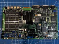
Anyone up for some IIcx troubleshooting assistance? We have clocks but no activity...
- Thread starter Sideburn
- Start date
")
GRudolf94
Well-known member
The reset trigger signal is fed into pin 7 of UB15 and UA15, and each generates one reset signal on pin 6 (/RST_A and /RST_B or somesuch). Have you checked that both see a reset button pulse or a signal coming up to 5V on pin 7? Only then should anything happen on pin 6 of either. Also consider the weird pin numbering on PLCC packages. Another thing: the sony sound ICs need 12V to work. Check if that's present there.
GRudolf94
Well-known member
Just checked, Bomarc calls them ARST and BRST but meh.The reset trigger signal is fed into pin 7 of UB15 and UA15, and each generates one reset signal on pin 6 (/RST_A and /RST_B)
Sideburn
Well-known member
Yes... Im using the same schematicJust checked, Bomarc calls them ARST and BRST but meh.
Sideburn
Well-known member
The reset trigger signal is fed into pin 7 of UB15 and UA15, and each generates one reset signal on pin 6 (/RST_A and /RST_B or somesuch). Have you checked that both see a reset button pulse or a signal coming up to 5V on pin 7? Only then should anything happen on pin 6 of either. Also consider the weird pin numbering on PLCC packages. Another thing: the sony sound ICs need 12V to work. Check if that's present there.
ok pin 7 is going from 4.7 to 3.8 when i hit reset.
ARST is now dropping from 4.7 to 0 when i hit reset (checked pin 13 of the 68882 / UC8)
pin 6 of UA15 is going low and high when i hit reset and it seems to be timed by 25ms or so.... i can hit the button quick and pin 6 has to "catch up"..
pin 6 of UB15 is doing the same i hit reset and then watch it go low and high...
pin 12 of UA15 and UB15 have 12v.
Sideburn
Well-known member
ive noticed... its saying pin 15 of UA15 is going to R17 (the bodge i had to make) but it is going to R7Bear in mind those tend to contain mistakes. Better than nothing sometimes, but shouldn't be taken as gospel.
Sideburn
Well-known member
OK I need some help here. looking at the schematics I dont see which lines are STATUS do you mean STATUS on J12 of the 030? J12 is sitting low when i hit reset. I did a single shot capture on the o'scope and nothing.Ok, so you have reset and a machine that starts to execute. I would look at the status lines on the 030 - the first thing the ROM does after it's done with initial startup is, as @Phipli mentioned before, use the VIA to remap itself. Check if that happens.
Phipli
Well-known member
OK I need some help here. looking at the schematics I dont see which lines are STATUS do you mean STATUS on J12 of the 030? J12 is sitting low when i hit reset. I did a single shot capture on the o'scope and nothing.

You want bit 4 of port A I think this means. So, if port A is labelled from 0 to 7, thats PA4.
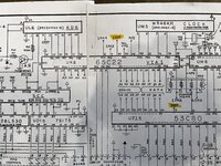
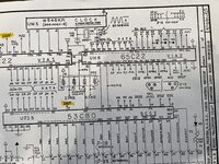
Can you share the picture of VIA1 from your schematic?
Sideburn
Well-known member
Pics and pdf attachedView attachment 58864
You want bit 4 of port A I think this means. So, if port A is labelled from 0 to 7, thats PA4.
Can you share the picture of VIA1 from your schematic?
Attachments
Phipli
Well-known member
Pin 6 according to that.Pics and pdf attached
Does it change state after you press the reset button?
Sideburn
Well-known member
Ahh, yes i checked all those already..@Sideburn by status lines I mean the controls signals that tell us what the CPU is doing. Such as R/W, !DTACK and others, not the literal status signal. Sorry for the confusion. Also check /BERR and... Maybe /HALT?
Stuck high and no change after reset.. most pins on that chip are the same.. stuck high, some low but no change on reset.Pin 6 according to that.
Does it change state after you press the reset button?
GRudolf94
Well-known member
I mean, just in case they were doing something different now, heh. One important thing when debugging m68k machines is knowing what those mean, and when they should be active. If /BERR is always asserted, that means there's always a bus error, so we look there. If /DTACK is never asserted, we know that no transaction is being acknowledged as successfully completed (at least in macs - some machines ground DTACK), etc.Ahh, yes i checked all those already..
Stuck high and no change after reset.. most pins on that chip are the same.. stuck high, some low but no change on reset.
Sideburn
Well-known member
Ahhh yes i had already checked those but I just re-checked them now that I have the sound chips in and they all are stuck high and no change on reset (R/W, DS, AS, BERR, DSACK)@Sideburn by status lines I mean the controls signals that tell us what the CPU is doing. Such as R/W, !DTACK and others, not the literal status signal. Sorry for the confusion. Also check /BERR and... Maybe /HALT?
Phipli
Well-known member
Thats good, the VIA is telling the GLU to overlay the ROM.Stuck high and no change after reset.. most pins on that chip are the same.. stuck high, some low but no change on reset.
It should go to pin 49 of the GLU chip. Does that have continuity to the top of the pin?
Phipli
Well-known member
Good point. Got distracted by the lack of sound chips.Looking back at the start of the thread, you said the CPU doesn't get warm. What do you have for 5V at the CPU, and what for a clock?
Similar threads
- Replies
- 7
- Views
- 675