• Updated 2023-07-12: Hello, Guest! Welcome back, and be sure to check out this follow-up post about our outage a week or so ago.

Anyone have a 12" Monochrome Display?

apm

Well-known member
I'm working on repairing a non-functioning Macintosh 12" Monochrome Display. The proximate cause seems to be that resistor RP13 is missing -- completely gone, nowhere to be found, nothing but a blackened set of pads left behind. The underlying fault appears to be that DP5 has shorted, but replacing it doesn't do me much good until I figure out what to replace RP13 with.

Does anyone have one of these displays who could open it and post a photo of the main PCB? RP13 is just behind the mains socket, though I can't even tell if it was originally a through-hole or surface mount part.

 

apm

Well-known member
I've worked out a schematic for quite a bit of this monitor by now. It has some similarities for the later Classic analog board, though with considerably more complexiy in the video circuit for various types of geometry correction.

The CRT neck board looks like a pretty good design on which to base a grayscale adapter for compact Mac CRTs. More on that later.

In the meantime, replacing DP5 (an 18V zener which was shorted) and trying 22k or 47k for RP13 results in a "flup-flup-flup" power cycling where the LED transiently comes on and then the system powers down, repeating the cycle about 2 times per second. It's possible a different RP13 is needed (anyone have one of these monitors??). But I'm wondering what else might cause this problem.


techknight

Well-known member
I have never seen a schematic or this monitor at all, or know its design. 

But if RP13 is a pass resistor for a zener diode, its in the Ohms, not K ohms. 

But that all depends on the current requirement, and the wattage of the original zener. 

You also need to figure out why that zener shorted, Can you tell me what circuit the 18V Zener is in? 


Trash80toHP_Mini

NIGHT STALKER
I wonder if the docs for the "Poor Man's Grayscale" hack for the SE/30 is still around. I know it was mostly a yoke swap, but there may be some info on the 12" donor display's electronics to be had there.


techknight

Well-known member
I have had the original neck board in an SE showing grayscale pretty decently. I have to jog my memory on how I did it, but I did. 


techknight

Well-known member
No this was circa 2005 or so, bak when I was first expiramenting with trying to run VGA on an SE. (which didnt work obviously, but the lower resolutions did). 

 
Last edited by a moderator:

Trash80toHP_Mini

NIGHT STALKER
If you can dig up some info, post it in a hacks thread. bbraun's bit banging of the SE output and dsiplaying it in two bit grayscale(?) would be a neat trick.

Back to the 12" 640x480 Grayscale ZaTopper, I wish I had one, so much nicer than my pair of RGBs. :/


Gorgonops

Moderator
Staff member
If you can dig up some info, post it in a hacks thread. bbraun's bit banging of the SE output and dsiplaying it in two bit grayscale(?) would be a neat trick.
Are you bringing up that "SE supports grayscale" thing we've debunked a bunch of times before again? TL;DR, it doesn't, at *all*, in hardware. Full stop.


Trash80toHP_Mini

NIGHT STALKER
Don't recall any debunking at all, my bad. I just remember SCSI Video adapter(?) capability of doing limited GS and Color on pre-color ROM Macs like the SE. Was that entirely software sleight of hand? Some of the stuff I read seemed to imply a hardware component?


Gorgonops

Moderator
Staff member
Was that entirely software sleight of hand? Some of the stuff I read seemed to imply a hardware component?
As explained last time, yes, entirely software unless you consider software stored in ROM "hardware".

The original Quickdraw isn't *entirely* monochrome; it technically supports handling images using the eight named colors produced by an Imagewriter printer with a color ribbon. Because Quickdraw is used for both display and printer output it is indeed possible to use software in conjunction with an *entirely external and separate from what is built into the machine* device to create a "color display" that works with *some*, not a lot of, software. (Conceptually those SCSI displays are more like a live-updated print preview than a normal bitmap plane, which breaks many things.)

Again, there is *no where* in the SE's actual display hardware any capacity to produce grayscale or color images that's just waiting to be unleashed. Any "hack" to get grayscale out of it will amount to a complete new video card, and it will *not* be compatible with almost any off the shelf software because true Grayscale is a color Quickdraw concept. That "spot color" support in Pre-SE/30s has no idea about it.

Again, I'd swear this has come up at least twice before...

 
Last edited by a moderator:

Trash80toHP_Mini

NIGHT STALKER
It might have come up in a thread we had a while back on the ScuzzyGraph, which might well be the only implementation of this stuff ever? All the later SCSI Display Boxen required Color ROMs.


CC_333

Well-known member
I vaguely recall reading about this subject a few months ago, which drew pretty much the same conclusions: pre-SE/30 compacts can't do Grayscale because there's no hardware support, and even if there were (via some sort of hack or something), the software (firmware?) in the ROM only contains the original QuickDraw, which doesn't understand color as we know it on later Macs. Not to mention the fact that the SSW doesn't really support color in any meaningful way until System 6 or 7 (which brings us back to the ROM, because color support within the SSW depends on there being support for the same in ROM).

Workarounds exist (the aforementioned ScuzzyGraph, for example), but many (most?) are very suboptimal and highly incompatible with most normal software.

Am I understanding this properly?

c

 
Last edited by a moderator:

apm

Well-known member
I have never seen a schematic or this monitor at all, or know its design. 

But if RP13 is a pass resistor for a zener diode, its in the Ohms, not K ohms. 

But that all depends on the current requirement, and the wattage of the original zener. 

You also need to figure out why that zener shorted, Can you tell me what circuit the 18V Zener is in? 
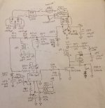
DP5 is on the primary side of power supply. Why it shorted I'm not sure. See attached reverse-engineered schematic. (Apologies for low-quality photo; no time to format this properly right now.) A few components I couldn't read the value, especially the SMT caps. 

In any case, I believe RP13 serves as a kickstart to the TDA4605 by providing a trickle of current from the unrectified mains line. It looks like after the circuit starts up, the winding of ZP1 pins 3-4 would provide a source of continuing power to the TDA4605. In a circuit in the datasheet for the TDA4605, a similar resistor to RP13 has a value of 75k. I tried 47k and then 22k, which is what's in the later Classic analog board. Same result in each case. I don't think it could go much lower without needing a >2W part, which doesn't seem likely given the size of the pads.

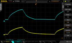
I can't put a scope on the primary side of the circuit, but I did scope the secondary side tonight. There are two secondary voltages, a higher one used for horizontal sweep and the CRT neck board, and a lower one powering most of the rest of the circuits. See attached. Both voltages rise together until they reach around 50V and 18V, at which point the regulator shuts off, and the cycle begins again 500ms later. I don't know what the voltages ought to be when stable, but I'm wondering if this is an over-voltage crowbar circuit kicking in.

In the brief period these two voltages are active, the horizontal sweep runs: I can see a periodic signal on the gate of the HOT, and voltages appear on (at least) one of the flyback secondary windings. 

IMG_5507.JPG

DS2_20181013211647.png


techknight

Well-known member
Ok, I get it now. seems as if this monitor and the Classic analog board were probably engineered, if not manufactured by the same company. 

and your right, the 18V zener supplies the necessary VCC for the switching IC. 

if the 18V zener is shorted, it was either caused by a surge, or the failure of the 4605. 

Either way, the 4605 probably took some damage. Keep an eye on Pin 1 because its waveform vs the internal reference voltage is critical for the circuit to go into regulation. anything there out of the norm will tell you if its going into undervolt, overvolt, overcurrent, loop loss, etc... 

Set your scope on dual trace mode as you have it, and reference each channel to pins 1 and 7. See whats going on, compare against operation details of the TDA4605 datasheet. Only way your going to nail this sucker. Obviously safety first since your on the hot side of the system, isolation transformer on the scope is a must. Also the VCC input has undervolt protection as well, so when the supply cycles up, if the VCC doesn't come up to a certain point, it locks out as well. I like the datasheet of these older ICs because they explain paragraph by paragraph setp by step exactly how the IC works and what you should expect during normal, and overload/no load abnormal operations. 

One other thought, have you done some basic troubleshooting in the secondaries? Such as making sure the HOT isnt shorted? things like that to rule out overcurrent/undervolt cycling? 

 
Last edited by a moderator:

apm

Well-known member
Good thoughts, thanks. I think the HOT and its driver (TEA2037) are okay: there's a sensible signal at the HOT gate (not itself diagnostic), and a reasonable voltage appears on the one flyback secondary I felt comfortable to test with a 10x probe. When I retrieve my 100x probe from the office I can probe the higher-voltage parts of the horizontal circuit, but it looks like that's not the source of the problem.

I will have to get my hands on an isolation transformer. Any particular reason to put the isolation transformer on the scope rather than the monitor? 

I guess I could also just try replacing the TDA4605 and see what happens.


techknight

Well-known member
I will have to get my hands on an isolation transformer. Any particular reason to put the isolation transformer on the scope rather than the monitor? 


Personal choice honestly, But keep in mind you have to isolate the 3rd prong/grounds. Thats the reason for the transformer, because if something oddball is wrong, the minute you ground your scope on the primary side of the SMPS, BOOOOOOOOM


apm

Well-known member
I replaced the TDA4605 and recapped the whole board. Not sure if the results are progress. Now with the video cable unplugged, the monitor powers up and makes an ominous sizzly noise. I think it's coming from the flyback but I'm disinclined to get close enough to really pinpoint the source. I may have heard a couple arcs, but I can't see anything even with the lights off. There's a dim raster that overscans the CRT.

With the video cable plugged into a Mac which is turned off (i.e. no signal), the sizzling stops and I get a bright white raster, wider than the screen and a bit too short [1]. With a video signal present, it goes back to power cycling like it did before.

So where's the sizzling coming from and why? Damaged flyback perhaps, or maybe damaged sweep IC (TEA2037)? Perhaps even an ongoing power supply problem: I don't have a meter or scope to hand right now, so I can't check the voltages. Perhaps they are still too high.

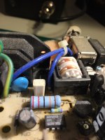
As it happens, I was able to do some testing on a working unit recently. The normal power supply voltages are around 40V and 12V (mine would rise to 50V and 18V before shutting down). The mystery RP13 is a vertical ceramic resistor of some sort -- see picture -- which is unlabelled but (from memory) measured between 5k and 6k.

[1] That plugging in a cable, even without signal, changes things is not unexpected from what I understand of the schematic. There are a few odd bits of circuitry on the analog board which take their input from one of the monitor sense pins that's grounded when you plug it into a Mac. One bit of circuitry looks like it would increase the voltage to the flyback primary by maybe 2V when a Mac is connected. Another looks like it would add a 1200pF capacitor in parallel between the drain of the HOT and ground. I'm not sure what purpose either of these circuits serves or why they were designed in.

IMG_5837.jpg

 
Top