• Updated 2023-07-12: Hello, Guest! Welcome back, and be sure to check out this follow-up post about our outage a week or so ago.

Another Malfunctioning Macintosh II Power-on Circuit

davidg5678

Well-known member
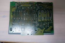
As referenced in a previous thread, I am working on restoring a Macintosh II. This machine’s power-on circuit seems to be broken. 

The entire logic board has been recapped and cleaned to the best of my ability -I also repaired several damaged traces. Two 1/2 AA batteries have been installed in sockets. When I press the power button on my keyboard or at the back of the machine, nothing happens at all. I am able to run an alligator clip from one of the batteries to the rightmost PSU pin in order to jump-start the computer, but this is definitely less than optimal. I checked the PSU voltages under load and verified they are all within .2ish volts of normal. I also noticed that when the machine is powered off and I read voltage between the rightmost PSU pin and ground, I can make the value spike to .6 volts from 0 volts upon pressing the keyboard power button. I am not sure if this is normal behavior. (maybe someone can verify?)

After being recapped with repaired traces, is there any obvious reason I have these issues? Please let me know if you have any ideas. Thank you!

I am happy to provide more information and/or photos.


LaPorta

Well-known member
Photos would be great. I remember that I had a trace gone that didn’t look bad but was, leading from the left side of the board, under the RAM slots, to the upper right part of the board...so I bypassed it underneath. Perhaps you have something similar going on.


AwkwardPotato

Well-known member
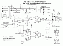
When dealing with a similar issue on my IIx, this schematic (courtesy of http://home.earthlink.net/~gamba2/) came in very handy:

macIIsch.GIF

For reference, the PSU pin you used to jumpstart the computer is labeled "J18-15, Power Supply control."

Since you said pressing the keyboard power button brings the PSU control pin to around 0.6V, I'm wondering if there's some issue around Q3. Definitely check for continuity around the NAND gates labeled UB2, since these control the power-on circuit. Measure the voltage on pin 8 of UB2 too, this should be 0V when the keyboard switch is pressed. Measure the voltage at the emitter of Q3, it should be around 5-7V at all times.

In a working power-on circuit, gates 3 and 4 (rightmost ones in the power-on circuit) should output 5-7V when neither switch is pressed, until one of the switches is pressed, at which point it goes to 0V. The output of those gates then goes to the base of the PNP transistor at Q3. To turn on that transistor (let current flow from the emitter to the collector), the voltage at the base should be lower than that at the emitter (which is always at 5-7V). Since the collector is connected to the pin that turns on the power supply, the base needs to be pulled to 0V to turn on the computer.

 
Last edited by a moderator:

davidg5678

Well-known member
Thank you for your responses -I apologize for the delay as I was on vacation.

After writing my original post I decided to check the voltage of the batteries inside the mac. I had figured both batteries would be working as I had installed them brand new the month before. To my surprise, one of the batteries was reading .6 volts and the other 3.6 volts. I replaced the .6 volt battery with a brand new one and the computer's power circuit started to behave slightly better. I was able to use soft power unreliably for about an hour until it stopped working again. The voltage on the Power Supply Control pin was even closer to the 5 volts it should be instead of the .6 volts from before.

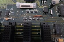
I went on vacation after this and upon returning found that my brand new battery had been drained to about .6 volts. The other battery was still normal. I checked the voltages that AwkwardPotato suggested but found them all to be at least a volt too low. --Maybe this is due to one the dead batteries? I also noticed that the legs of Q3 and Q4 looked slightly less shiny than their surroundings. I will try to reflow these with fresh flux and solder. 

Is there anything that would cause the battery to die so quickly while the computer was unplugged?

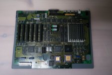
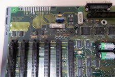
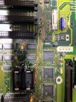
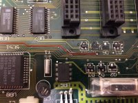
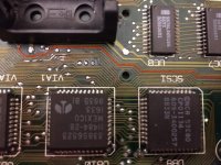
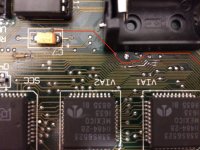
I have attached some pictures of the motherboard.

Thanks again!!

_1040235.jpg

_1040239.jpg

_1040244.jpg

_1040249.jpg


AwkwardPotato

Well-known member
What's the resistance between the battery terminals? I wonder if something's shorted and it's draining the battery. Strange issue indeed.


davidg5678

Well-known member
What's the resistance between the battery terminals? I wonder if something's shorted and it's draining the battery. Strange issue indeed.
Can you explain how to do this? I set my multimeter to ohms and measured between the two sides of the battery holder, but couldn't get any reading.

I also noticed that the legs of Q3 and Q4 looked slightly less shiny than their surroundings. I will try to reflow these with fresh flux and solder. 
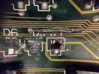
Trying to do this has created a much larger problem. Some of these reflowed without a problem, but it looks like the pads on a few were terribly corroded as they fell apart when they were touched by my iron. I am now left with some destroyed pads and a very damaged trace to repair. 

Does anyone know the way to repair something like this?

Thank you!

IMG_2221.jpg


AwkwardPotato

Well-known member
Sounds like you tested the resistance correctly, so I'm at a loss for what the issue is with the battery if you're not getting anything on the multimeter. Maybe that brand of battery is problematic? Hopefully someone else can chime in on that.

To fix that trace, remove the damaged part of the trace with an x-acto knife, but leave a bit of the little undamaged piece attached to the via (just enough to solder to). Use the knife to scratch away a bit of the solder mask (green coating) on the ends of the traces that need to be attached, and clean up that area of the board thoroughly with IPA. Tin the exposed ends of the traces and run a piece of 30AWG wire-wrap wire (spools of this can be found on Amazon for under $10) from one end to the other. Clean up the area with IPA and upload another picture before working on the missing pads.

BTW, what kind of soldering iron are you using? If the temperature is adjustable, try lowering it a bit since the heat probably didn't help the pads. Also, make sure you're not heating the joint for too long (no more than say 5 seconds), since that will also damage the pads. After adjusting the temperature, you might want to touch up the pin on D4 that's in the top-right in that photo, since it looks like it isn't making a reliable connection.

 
Last edited by a moderator:

davidg5678

Well-known member
Thanks for the suggestions!

I have successfully patched the trace. I initially tried to cut away the destroyed chunk of trace and run a patching strand of wire but damaged the ends of the trace too much to allow for it to happen. I then decided to run a wire from point to point instead. Because I would have had extraordinary difficulty following the trace by hand, I took several pictures of the board and drew a line following the trace's path on my computer. (See attached images.) After this, it was easy enough to just run the wire. I now need to figure out a way to keep it from accidentally getting ripped from the board...

My current soldering iron is a standard 40 watt Weller that has no temperature adjustment features. It has worked well in the past, but it might be time to get a nicer soldering station.

I was able to clean up the pins on the rest of the components and make them shiny again. --Now for attempting to repair the pads and replacing the destroyed components. Does anyone know what part would be a suitable substitute for D5 and D6? It looks like they are a sort of surface mount transistor.

E61440AD-CF09-42D7-A698-A0F76B5F463B.JPG

IMG_2222.jpg

IMG_2224.jpg

IMG_2225.jpg

 
Last edited by a moderator:

Johnnya101

Well-known member
As for a soldering iron, I HIGHLY RECOMMEND getting a Hakko FX888D. Cheap (Think I got mine for $120), very nice quality, temperature control, just all around nice. A lot of pros use them. I find it hard to burn anything with mine.


LaPorta

Well-known member
The way I got around the wire-on-the-board issue was to run it from point to point underneath the board instead. Also, get wire thin enough to push through the hole, which is what I did as well. Works great, and you can't even notice it (though yours is kind of ripped up anyway).


AwkwardPotato

Well-known member
I now need to figure out a way to keep it from accidentally getting ripped from the board...
A small dab of hot glue near the solder joints (but not on the solder joints) works well to anchor the patch wire down and prevent it from being ripped up. 

Does anyone know what part would be a suitable substitute for D5 and D6? It looks like they are a sort of surface mount transistor.
D5 and D6 are MMBD914 diodes. They can be purchased here.

 
Top