Success!
With a little help (okay, a lot of help) from
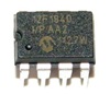
@zigzagjoe, TashSync is now working on the IIsi without an external power supply! He noticed that the PIC's own protection diodes could be used in lieu of external diodes to rectify the composite sync signal to provide power as long as there was enough of a bulk capacitor between the supply and ground pins, and lo and behold, it works! At around 2.8 volts, the voltage it runs off is nothing to shout about, but it's enough, and it's stable.
Circuit (TI-83 Plus style):
View attachment 88889
Thoughts? Is this crazy or just-crazy-enough-to-work?


")


