Here’s a step-by-step guide explaining how to disassemble a QuickTake 100. It should be identical for a QT150. It is difficult to do, but hopefully this guide will help. Make sure you keep your screws organised in a jewelery box or something similar with compartments, as there are a lot of them.
Here is a link to a Mouser project.
To begin, remove a 5.8mm screw next to the tripod mount.

Remove a long 28mm screw holding the top and bottom housings together.

Remove a 5.3mm screw from inside the battery compartment.

Remove a 5.3mm screw securing the fascia, next to the eye cup.

The rear fascia can be lifted away now.

First, lift away the acrylic lens covering the LCD and store it somewhere safely.
Notice a clip which you can gently lever up, enabling you to lift away the top half of the outer casing.

Now you will see the top PCB EP02A-4. Here you must:
- Remove 3x 4mm black screws with large heads
- Remove 1x 4.8mm silver screw
- Disconnect 2x ribbon cables and 1x JST connector.

Desolder 8x coloured wires from the corner of the PCB:

Also desolder a black ground wire on another corner:

The board is ready to be lifted away and put aside for recapping.
On the top side there are 2x electrolytic capacitors that need replacing. They are in an unusual form factor which makes recapping more complex.

Underneath are 7x electrolytic capacitors that need replacing.

As you see they are just a regular electrolytic cap encased in plastic. These aren’t available in this form factor anymore.

To remove them, snip the leads near the pads with a pair of side cutters, then use hot air (but turned down low, to 100˚C) to soften the glue at which point the plastic casing can be pried up with a flat blade.

For reference this is how I’m replacing them – with regular radial capacitors with their legs bent over.

Here’s this particular board done.

One of the very smallest caps is a tantalum as I couldn’t find a small enough radial cap, it fits nicely across the pads.

Back to the main housing, optionally remove the CCD flat flex cable, and the red LED lens (be careful as it’s easily lost), and store them safely.

The LED sits inside a little black housing – take note of how it’s fitted to the casing for reassembly.

Also note these two moving points of contact for the door covering the serial and DC in ports, these should be cleaned and regreased.

The battery door now needs to be unhooked from the two plastic nubs holding it in. With a pointy tool, press into the centre of one of the hinges to unhook it.


Next remove 2x 6.4mm screws – 1 from the inside edge of the housing by the viewfinder, and another by the battery bay.

As you lift out the inner frame from the lower casing, be sure to disconnect this small cable for the lens cover sensor.

Orient the camera so that the LCD is facing you. Remove 2x 4mm screws from the PCB, but don’t lift it out yet.

Disconnect this little cable from the JST header.

Now lift this small PCB away from a larger PCB, it is held in by a single connector.

With the LCD board lifted out, note how the coloured cables are routed for when you come to reassemble.

There’s a supercapacitor on the back of the LCD board that needs swapping out.

Turn your attention to another large PCB, EP03A-4. Again there are cables, screws and wires that need removing.
– Remove 3x 4mm screws with large heads
– Remove 1x 4.8mm screw with a silver head.

Note the silver headed 4.8mm screw attaches to a long post on the other side.

Remove this small flat ribbon connector labelled ‘shutter’.

Coming back to the large PCB, desolder just the black wire.

You are ready to lift the EP03A-4 PCB out.
Take note of the routing of the flat flex cable through the main housing for when you come to reassemble.

The PCB is held in by a couple of small connectors, so gently lever it out on the same side.

Here is a view of the board partially lifted out, which might be useful during reassembly.

Now the board is free, disconnect flex cable labelled ‘process’ and 2x small harnesses with JST connectors.

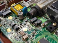
Here’s the board view, top side, featuring 3x odd shaped capacitors. Also, there are many more hiding inside that metal box.

Here's the underside of the board with 5x electrolytics. Pay special attention here to mounting the new caps flush as clearance against the lower casing is limited.

The metal box now needs removing from the PCB:
– Underneath: 10x pins to desolder
– On top: 2x large solder joints securing the metal case to the ground plane.
Once you have done this the box should lift away. It will definitely need some gentle teasing and patience.

You then need to desolder the small PCB EZ01A from the metal case on either side, after which it can be pried out. The board comprises tightly packed components, with a mixture of through hole and SMD capacitors.

Here’s mine after desoldering – some caps had leaked – and after recapping.
The purple caps are polymers, they can’t leak but I decided to replace them anyway since ESR and capacitance can drift over time.

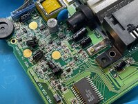
Back to the camera now, this is the flash PCB that we need to get access to next.

Remove these two 5.7mm screws holding a detachable section of the frame.

Disconnect this small cable, with yellow and black wires.

Now you can separate this part of the frame.

Desolder this blue wire.

Remove 2x 4mm screws holding the flash PCB in place.

Remove a small screw holding a ring terminal to the flash bulb housing.

Lift out the flash bulb housing

To be continued...
EZ01A
EP02A-4
EP03A-4
EP04A
EP05A-4
| Capacitor | Value | Size in mm (length x dia) | Notes |
|---|---|---|---|
| C1 | 47μF 10V | 10 x 6.3 | 105˚C, OS-CON |
| C7 | 33μF 10V | 6 x 5 | |
| C11 | 220μF 25V | 16 x 8 | 105˚C, Low Impedance |
| C12 | 6.8μF 25V | 5.5 x 4 | |
| C13 | 270μF 10V | 15 x 6.3 | 105˚C, Low Impedance |
| C14 | 10μF 25V | 5.5 x 5 | |
| C17 | 270μF 10V | 15 x 6.3 | 105˚C, Low Impedance |
| C22 | 47μF 10V | 10 x 6.3 | 105˚C, OS-CON |
EP02A-4
| Capacitor | Value | Size in mm (length x dia) |
|---|---|---|
| C201 | 47μF 6V | 7.2 x 4.7 |
| C202 | 47μF 16V | 12.2 x 4.7 |
| C203 | 4.7μF 10V | 5.3 x 4 |
| C204 | 10μF 16V | 5.3 x 4 |
| C205 | 1μF 50V | 5.3 x 3 |
| C206 | 47μF 6V | 7.2 x 4.7 |
| C208 | 47μF 6V | 7.2 x 4.7 |
| C210 | 47μF 6V | 7.2 x 4.7 |
| C250 | 10μF 6V | 5.3 x 4.7 |
EP03A-4
| Capacitor | Value | Size in mm (length x dia) |
|---|---|---|
| C301 | 47μF 6V | 7.2 x 4.7 |
| C302 | 47μF 6V | 7.2 x 4.7 |
| C303 | 47μF 6V | 7.2 x 4.7 |
| C304 | 47μF 6V | 7.2 x 4.7 |
| C305 | 47μF 6V | 7.2 x 4.7 |
| C307 | 47μF 6V | 7.2 x 4.7 |
| C308 | 47μF 10V | 9.4 x 4.7 |
| C329 | 47μF 6V | 7.2 x 4.7 |
EP04A
| Capacitor | Value | Size in mm (length x dia) | Notes |
|---|---|---|---|
| C411 | 0.47F 5.5V | 7.8 x 10.7 | Supercapacitor |
EP05A-4
| Capacitor | Value | Size in mm (length x dia) | Notes |
|---|---|---|---|
| C501 | 100μF 10V | 7 x 6.3 | 105˚C |
| C504 | 180μF 300V | 42 x 13.6 | Labelled 'PHOTO-FLASH' |
Here is a link to a Mouser project.
To begin, remove a 5.8mm screw next to the tripod mount.
Remove a long 28mm screw holding the top and bottom housings together.
Remove a 5.3mm screw from inside the battery compartment.
Remove a 5.3mm screw securing the fascia, next to the eye cup.
The rear fascia can be lifted away now.
First, lift away the acrylic lens covering the LCD and store it somewhere safely.
Notice a clip which you can gently lever up, enabling you to lift away the top half of the outer casing.
Now you will see the top PCB EP02A-4. Here you must:
- Remove 3x 4mm black screws with large heads
- Remove 1x 4.8mm silver screw
- Disconnect 2x ribbon cables and 1x JST connector.
Desolder 8x coloured wires from the corner of the PCB:
Also desolder a black ground wire on another corner:
The board is ready to be lifted away and put aside for recapping.
On the top side there are 2x electrolytic capacitors that need replacing. They are in an unusual form factor which makes recapping more complex.
Underneath are 7x electrolytic capacitors that need replacing.
As you see they are just a regular electrolytic cap encased in plastic. These aren’t available in this form factor anymore.
To remove them, snip the leads near the pads with a pair of side cutters, then use hot air (but turned down low, to 100˚C) to soften the glue at which point the plastic casing can be pried up with a flat blade.
For reference this is how I’m replacing them – with regular radial capacitors with their legs bent over.
Here’s this particular board done.
One of the very smallest caps is a tantalum as I couldn’t find a small enough radial cap, it fits nicely across the pads.
Back to the main housing, optionally remove the CCD flat flex cable, and the red LED lens (be careful as it’s easily lost), and store them safely.
The LED sits inside a little black housing – take note of how it’s fitted to the casing for reassembly.
Also note these two moving points of contact for the door covering the serial and DC in ports, these should be cleaned and regreased.
The battery door now needs to be unhooked from the two plastic nubs holding it in. With a pointy tool, press into the centre of one of the hinges to unhook it.
Next remove 2x 6.4mm screws – 1 from the inside edge of the housing by the viewfinder, and another by the battery bay.
As you lift out the inner frame from the lower casing, be sure to disconnect this small cable for the lens cover sensor.
Orient the camera so that the LCD is facing you. Remove 2x 4mm screws from the PCB, but don’t lift it out yet.
Disconnect this little cable from the JST header.
Now lift this small PCB away from a larger PCB, it is held in by a single connector.
With the LCD board lifted out, note how the coloured cables are routed for when you come to reassemble.
There’s a supercapacitor on the back of the LCD board that needs swapping out.
Turn your attention to another large PCB, EP03A-4. Again there are cables, screws and wires that need removing.
– Remove 3x 4mm screws with large heads
– Remove 1x 4.8mm screw with a silver head.
Note the silver headed 4.8mm screw attaches to a long post on the other side.
Remove this small flat ribbon connector labelled ‘shutter’.
Coming back to the large PCB, desolder just the black wire.
You are ready to lift the EP03A-4 PCB out.
Take note of the routing of the flat flex cable through the main housing for when you come to reassemble.
The PCB is held in by a couple of small connectors, so gently lever it out on the same side.
Here is a view of the board partially lifted out, which might be useful during reassembly.
Now the board is free, disconnect flex cable labelled ‘process’ and 2x small harnesses with JST connectors.
Here’s the board view, top side, featuring 3x odd shaped capacitors. Also, there are many more hiding inside that metal box.
Here's the underside of the board with 5x electrolytics. Pay special attention here to mounting the new caps flush as clearance against the lower casing is limited.
The metal box now needs removing from the PCB:
– Underneath: 10x pins to desolder
– On top: 2x large solder joints securing the metal case to the ground plane.
Once you have done this the box should lift away. It will definitely need some gentle teasing and patience.
You then need to desolder the small PCB EZ01A from the metal case on either side, after which it can be pried out. The board comprises tightly packed components, with a mixture of through hole and SMD capacitors.
Here’s mine after desoldering – some caps had leaked – and after recapping.
The purple caps are polymers, they can’t leak but I decided to replace them anyway since ESR and capacitance can drift over time.
Back to the camera now, this is the flash PCB that we need to get access to next.
Remove these two 5.7mm screws holding a detachable section of the frame.
Disconnect this small cable, with yellow and black wires.
Now you can separate this part of the frame.
Desolder this blue wire.
Remove 2x 4mm screws holding the flash PCB in place.
Remove a small screw holding a ring terminal to the flash bulb housing.
Lift out the flash bulb housing
To be continued...
Last edited: