-
Updated 2023-07-12: Hello, Guest! Welcome back, and be sure to check out this follow-up post about our outage a week or so ago.
You are using an out of date browser. It may not display this or other websites correctly.
You should upgrade or use an alternative browser.
You should upgrade or use an alternative browser.
Backlit Portable with broken display cable
- Thread starter Sherry Haibara
- Start date

Sherry Haibara
Well-known member
A few years older and possibly somewhat wiser, I've decided to revisit this project – especially in light of the recent progress with new hybrids and display cables being made.
As a quick rundown, the machine had been recapped already, so I left the caps alone. I've recently tried firing it up by connecting a bench power supply to the battery terminals (being careful to connect both positive leads and a negative lead), but I got absolutely nothing out of it. I then measured voltage on the +5V rail on Q16 and it measured 6.6V – the same amount I was supplying – so it seems the hybrid is feeding the battery voltage straight into the +5V rail. Not good.
I decided to check the hybrid situation, comparing my measurements to Androda's. Most of the measurements checked out, but there were a few notable exceptions:
- Pin 16 of the hybrid to Q1’s pin 2 showed high impedance, instead of the expected 4.4k ohms
- Pin 17 of the hybrid to Q1’s pin 3 showed high impedance, instead of the expected 9.6 ohms
- Pin 51 of the hybrid is disconnected from the positive side of C26, but is connected to R160
Digging deeper with the help of the schematics, I found out that there's no connection from R159 to C17 and R159 to Q1 pin 2, but there is continuity between C17 and Q1 pin 2 – suggesting an issue between R159 and C17. There's also continuity between R23 and Q1 pin 3, but no continuity between Pin 17 of the hybrid and R22. Finally, R22 and R23 themselves show high impedance when trying to measure their resistance.
All of this is suggesting problems with the power regulation circuit. I suspect that not only the hybrid might have gone bad, but the original caps around it might have corroded the board to the point of causing damage to R22 and R23 and severing a couple of traces.
With this in mind, I decided to test the rest of the board by supplying +5V directly to Q16, Q15 and Q20. When pressing the reset and interrupt buttons, this caused the machine to emit some garbled creaking noise from the speaker most of the times, but it did not want to go further – and it also pulled very little power (0.08A). Considering the issue with the +5V rail being fed battery voltage I had discovered earlier, I revisited TechKnight's suggestion that the SWIM chip might have gone bad, so I desoldered it and tried again.
With the SWIM chip removed, I can get the machine to make a happy chime most of the times. However, it seems like the machine powers itself off after 2-3 seconds, as the current goes down from 0.4A to 0.08A. Occasionally, the machine will boot with a sad mac chime instead – and interestingly, in this case it will not shut itself off, and it'll keep pulling 0.4A. In this second case, the display – with the reconstructed ribbon cable – becomes solid black.
I think this suggests the main logic should be somewhat functional, but I'd need help to investigate the problem further. I do have a donor PB 145 from which I could likely transplant the SWIM chip, but before I do that, I'd like to make sure nothing else is wrong with the machine, and also sort out the broken traces situation with the hybrid.
After all these years, I hope I'll be able to bring this machine back from the dead at last, and I'm happy to take any suggestions you may have. Thanks!")
As a quick rundown, the machine had been recapped already, so I left the caps alone. I've recently tried firing it up by connecting a bench power supply to the battery terminals (being careful to connect both positive leads and a negative lead), but I got absolutely nothing out of it. I then measured voltage on the +5V rail on Q16 and it measured 6.6V – the same amount I was supplying – so it seems the hybrid is feeding the battery voltage straight into the +5V rail. Not good.
I decided to check the hybrid situation, comparing my measurements to Androda's. Most of the measurements checked out, but there were a few notable exceptions:
- Pin 16 of the hybrid to Q1’s pin 2 showed high impedance, instead of the expected 4.4k ohms
- Pin 17 of the hybrid to Q1’s pin 3 showed high impedance, instead of the expected 9.6 ohms
- Pin 51 of the hybrid is disconnected from the positive side of C26, but is connected to R160
Digging deeper with the help of the schematics, I found out that there's no connection from R159 to C17 and R159 to Q1 pin 2, but there is continuity between C17 and Q1 pin 2 – suggesting an issue between R159 and C17. There's also continuity between R23 and Q1 pin 3, but no continuity between Pin 17 of the hybrid and R22. Finally, R22 and R23 themselves show high impedance when trying to measure their resistance.
All of this is suggesting problems with the power regulation circuit. I suspect that not only the hybrid might have gone bad, but the original caps around it might have corroded the board to the point of causing damage to R22 and R23 and severing a couple of traces.
With this in mind, I decided to test the rest of the board by supplying +5V directly to Q16, Q15 and Q20. When pressing the reset and interrupt buttons, this caused the machine to emit some garbled creaking noise from the speaker most of the times, but it did not want to go further – and it also pulled very little power (0.08A). Considering the issue with the +5V rail being fed battery voltage I had discovered earlier, I revisited TechKnight's suggestion that the SWIM chip might have gone bad, so I desoldered it and tried again.
With the SWIM chip removed, I can get the machine to make a happy chime most of the times. However, it seems like the machine powers itself off after 2-3 seconds, as the current goes down from 0.4A to 0.08A. Occasionally, the machine will boot with a sad mac chime instead – and interestingly, in this case it will not shut itself off, and it'll keep pulling 0.4A. In this second case, the display – with the reconstructed ribbon cable – becomes solid black.
I think this suggests the main logic should be somewhat functional, but I'd need help to investigate the problem further. I do have a donor PB 145 from which I could likely transplant the SWIM chip, but before I do that, I'd like to make sure nothing else is wrong with the machine, and also sort out the broken traces situation with the hybrid.
After all these years, I hope I'll be able to bring this machine back from the dead at last, and I'm happy to take any suggestions you may have. Thanks!
Sherry Haibara
Well-known member
Quick update:
1. I've added a patch wire from C26+ to Pin 51 of the Hybrid, and from R159 to C17+. They bypass two traces that went under the hybrid and that were most likely broken due to corrosion.
2. I've desoldered R22 and R23. They were both quite corroded, and after pulling them they showed the wrong resistance value. I spotted a broken trace near the bottom pad of R22, so I exposed a little bit of copper and joined the pad and the trace with some flux and solder.
3. I've spotted some signs of corrosion next to a couple of pins of the hybrid. After cleaning it up with alcohol, I've added some flux and reflowed the pins with my rework station.
With R22 and R23 removed, the symptoms are mostly unchanged. Powering it directly from Q16-Q15-Q20 consistently produces a happy chime, but the machine powers off after 3-4 seconds.
I've ordered replacements for both R22 and R23 and I'll attempt replacing them next weekend. Since they're involved in the battery voltage / charger section of the circuit, I'm hoping that the premature shutdown could be a result of the power manager not sensing the right voltage – though it's unclear to me if this could happen when feeding +5V straight to Q16-Q15-Q20. If I manage to get it working, I'll then focus on replacing the SWIM chip.
Sherry Haibara
Well-known member
I've made some additional (good) progress.
Since last time, I have:
1. Replaced R22 and R23
2. Repaired the broken trace between R22 and C27+
3. Repaired a broken trace between C25+ and pin 52 of the hybrid
I've also thoroughly washed the logic board with distilled water and soap, as well as IPA, scrubbing it gently with a toothbrush. There was some leftover cap goo in the area of the power manager and in a couple of other places.
With these changes, I can consistently get the machine to do a happy chime - and stay on – when powered via the hybrid bypass. The machine also reliably (and happily) chimes when booted using the hybrid, by pressing the space key. I've measured the voltage at Q16 and the +5V rail stays at a rock solid 5.47V when supplying 6.6V via the battery connector. The gate and source of Q16 are 2.3V and 6.3V respectively.
When the machine is on, the screen displays a solid black image. I think this may be the grey image expected in the absence of a SWIM chip, but darker – possibly due to issues with the manually re-built LCD cable.
I am observing some strange behaviour on the +5V hard drive rail and on the +12V rail, though. Specifically:
1. Q14 and Q15 have +280 mV on the gate, +6.3V on the source, and +6.3V on the drain.
2. Q20 has +5.7V on the gate, +6.3V on the source, and a slowly decreasing voltage on the drain that settles around +300 mV. However, I have measured (once) +3V on the gate, +6.3V on the source, and +5.2V on the drain.
I'm not sure if this behaviour is normal. The +12V rail is fine (+12.36V), but the disk +5V is not (as it comes directly from the drain of Q20). The -5V rail is also fine (measured -4.95V at pin 33 of the hybrid). Finally, I've also checked the voltage at pin 16 of the hybrid (+6.3V) and at C17+ (also +6.3V). Could this have anything to do with the absence of the SWIM? I see that section is controlled by SCSI +12V, and I'm not sure if it's already present that early in the boot process – in fact, I see +280mV at C22.
I'm fairly confident the main +5V rail is now stable, but I was unable to determine if the odd behaviour of the disk rail is due to an issue with the hybrid, if it's an issue somewhere else, or if it's actually expected. Ideally, I would like to determine this before I attempt a SWIM transplant.
I may also have the chance to test the machine with a non-backlit screen and see how that goes. I'd also appreciate any suggestions on how to check the remaining voltage rails.
Last edited:
GRudolf94
Well-known member
Having had it fed with 6.6V is a bit concerning - well past the threshold at which a fair few things would fail. How long did it run like that? Even now, having +5V at 5.47 puts it way past normal tolerance (5.25V), and close to the 5.5V max at which a fair few parts are rated to. That does seem like a hybrid/surrounding traces issue, and reason for concern.
Q14 and Q15 are supposed to be turned on with a gate pulled low - which is why you see "battery voltage" on either side. The gate to Q20 is controlled by Q24, which is turned on by Q25, and that is in turn controlled by PMGR. Unless the machine asks PMGR to turn on the disk rail, you'll not have 5V to the HDD. I think it only enables the disk halfway thru POST.
Do you have a way to scope screen signals? Check contrast voltage, but also CL1/CL2/FLM. A multimeter reading of average voltage might suffice there. I suspect silicon damage beyond the SWIM absence.
Sherry Haibara
Well-known member
Thanks Rudolf!
I've conducted the majority of the tests by supplying +5.2V directly to Q14, Q16 and Q20, and only run a limited number of tests with +6.6V on the battery connector. Yet, the original state of the machine (with the broken traces I've mentioned) had originally caused battery voltage to be exposed on the +5V rail of Q16. I think this is the main culprit behind the SWIM having failed. I can't exclude that either this, or the similar voltage on Q14's drain, might have caused additional silicon damage, though I would tentatively say that most of the logic should be intact (given the happy chime).
From what I understand, Q20 could be behaving normally. Q14 and Q15 are also being turned on correctly as their gate is pulled low, but they are not outputting the right voltage. Could this may be a failure of Q14 and Q15 themselves? I've read that sometimes a failed TO220 could output a higher voltage than expected when failed, but not sure if this could be the case here.
The +5V rail is also a bit high, indeed. The +5.2V I once measured on Q20 was actually way more in spec. There's also the possibility of some other component (or the hybrid itself) not working correctly and messing up the voltage regulation; the voltage on the source (+6.3V) of all those regulators seems fine to me, but perhaps something else is causing them to output a higher voltage than expected.
As for the display, sadly I don't have a scope, but I could try checking those signals with the multimeter.
GRudolf94
Well-known member
Q20 is behaving normally in that what's observed at the drain matches what's on the gate, as are Q14 and Q15 if their gates are being pulled low by the hybrid's pin 41 - 12V is generated by VR1 after being fed battery voltage via Q14/15. If Q14/15 were to only pass 5V, their gates would probably be connected to the gate of Q16 on hybrid pin 8, which should be a bit higher than pin 41.
5.2V on the 5V rail would've been fine. It feels like the hybrid is at fault here, as it tends to be quite often, due to the resistors printed on the ceramic substrate degrading with cap goo.
5.2V on the 5V rail would've been fine. It feels like the hybrid is at fault here, as it tends to be quite often, due to the resistors printed on the ceramic substrate degrading with cap goo.
Sherry Haibara
Well-known member
That makes sense. I was under the impression that Q14, Q15 and Q20 were expected to have +5V at the drain based on what I had read here, but that's not necessarily the case. Indeed, it would explain why Q14 and Q15 are driven by pin 41 rather than pin 8.
If that's the case, I wonder if there's a way to put a patch on the hybrid to lower the voltage on the 5V rail a bit. I was planning to replace it with Androda's new design, so if fixing the original one turns out to be impossible it would not be a big deal – but this message got me curious. Though that resistor would be on the hybrid itself, so I'm not sure it would be possible (or wise) to mess with it externally.
I am afraid the hybrid on this portable has suffered quite extensive damage from caps. It looked quite poorly before I cleaned it up, and the various broken traces around it that I fixed are not a good sign either. I really would not be surprised if that goo had caused the resistors on the hybrid to drift substantially.
GRudolf94
Well-known member
I haven't looked at the hybrid's internals as I don't have a portable myself, but any work on a ceramic substrate (not just the Portable's hybrid) requires silver solder - conventional solder alloys (i.e. chemically rips out) the traces right out of the ceramic, making the whole thing useless. If you're to put any further work into this, and it has a suspected-faulty hybrid, it'd be wise to just replace it outright. You're risking frying more stuff and making it harder on yourself to troubleshoot inaccurate voltage regulation.
Sherry Haibara
Well-known member
Before placing an order for a replacement hybrid and display cable, I've taken some additional measurements of the LCD signals. Here's what I found.
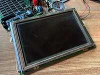
The display contrast voltage is +3.75V. On a happy chime, FLM is +262mV, CL1I is +308mV, and CL2I is +2.56V. On a death chime, the voltages are a little higher: FLM +293mV, CL1I +345mV, CL2I +2.9V.
As you can see from the attached picture, the display shows a solid black image. This is a backlit display and it doesn't seem to have electrolytic caps on its board, but the symptoms are identical to those of this thread (in that case, with C11 off).
This display has had its cable reverse engineered and rebuilt, so it's possible this could be an issue with the cable itself. I think I'll desolder the rebuilt cable and send the connector over to Androda to get it installed on a replacement one.
Attachments
Similar threads
- Replies
- 31
- Views
- 2K
- Replies
- 8
- Views
- 901
- Replies
- 29
- Views
- 2K
- Replies
- 2
- Views
- 313