• Updated 2023-07-12: Hello, Guest! Welcome back, and be sure to check out this follow-up post about our outage a week or so ago.

Backlit Portable with broken display cable

Sherry Haibara

Well-known member
Hi there!
The title says it all - I've recently acquired a Macintosh Portable "demo unit" (much alike the one who was being sold on ebay a couple of weeks ago) that was selling for a pretty low price and I'd be interested in getting it back to work.

The unit has multiple problems, including a dead hard drive, but probably the biggest one is that the video cable is broken - totally cut in two pieces. 
I know that earlier, M5120 portables had a ribbon cable that was easier to repair, but the backlit model unfortunately has a flex cable, so I guess I should pretty much rebuild the whole thing from scratch.

I looked around for information about how to do it without any luck - the only reference I've found is this old post from Uniserver, but the pictures are long gone. 
I know it's going to be painful and take a lot of time, but I'd really really like to have it alive :)


Sherry Haibara

Well-known member
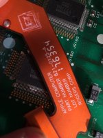
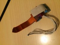
Just for reference, this is the cable I'm talking of.
I've thought about finding another flex cable with the same number of connections, but this cable here splits in two parts... 
Ideally, if someone had a spare, that'd be awesome; but I have a feeling finding a compatible part is going to be tough.

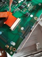
Does anybody know if the CN1 header is connected to the video cable somehow?

AhburxE9Ue_PhWUGLQAsz6-aumC4a9M-mLiu3Z1I4P9u.jpg

As2USsyWuMf5cQUZU7KDHAKlIklbz5CHbaSOIsT-Jj6n.jpg

 
Last edited by a moderator:

trag

Well-known member
Does anybody know if the CN1 header is connected to the video cable somehow?
If you have ah ohmmeter (one function of a multimeter) test continuity between the pins on CN1 and the video cable header.  If they're common, then it might be easier to adapt something.   

Digi-Key sells a wide variety of flat flex cables.  As you wrote, the difficulty is that this cable splits into two cables.  Also the turns in the cable are a small problem, although I think you can deal with those by creative folding -- but not too much folding.  Folding can easily break the conductors in the cable.

If CN1 connects, then it might be possible to get two flat flex cables from Digi-Key (or similar) which match the two smaller cables after the split.    They can be bought with flat ends suitable for connectors as shown in your picture, or with tinned pinned ends that might be matable with CN1 and cables with one end flat and the other end pinned are also available.


techknight

Well-known member
Most PCB fab places are starting to offer FFC services, so if someone could take the time to map it out into a new Gerber file it could be reproduced again. 

But I dunno how viable of an option that is. Worse comes to worse, figure out which connections are broken and then run wires. 

 
Last edited by a moderator:

Ferrix97

Well-known member
Good news! CN1 is connected to the flat flex connector!, maybe it was the connector for the non-backlit model.

At this point, I think I will make a new cable using very thin wire, the same I use to repair traces on logic boards.

then put all of the wires in a loom and route it to the display.

Soon I will start making the pin-mapping for both ends, I'll let you know!


unity

Well-known member
If you want the connector from a display with the cable I have a set. It would give you a head start. I even have spare mobos, I can probably pull the connector from a mobo. I dont think shipping will be all that much since it will be a pretty small package. It just make take a long time! Not sure how much of a rush you are in to complete it.

Also I am not familiar with the backlit models. Im not sure if there is a spot on the mainboard for a connector for this cable.


Ferrix97

Well-known member
Thanks for your help!

This is the other end, the plug is the same for both backlit and non-backlit, the backlit then goes to a flat flex. that joins the data and the backlight.

IMG_3213.JPG


unity

Well-known member
Hmmmm....

So the backlight cables route into the flex ribbon also? Well if you think the non-backlit cable will at least get you most of the way there let me know if you want it. Looks like you would still have to run some wires anyway for the power parts of the backlighting.

 
Last edited by a moderator:

Sherry Haibara

Well-known member
Yep, the flex cable carries both the backlight power and the video data: the two different types of signals are then split in two different cables, the one coming out of the blue plug goes to the motherboard and it's the same cable non-backlit portables use (with the difference, if I've understood the diagram correctly, that in the non-backlit the other side of the cable goes directly to the LCD assembly, with nothing in between), while the other goes to the inverter.
I'm not sure if we have the "motherboard-end" video cable, but I think we have!

The trouble here is that the two of them join in the same flex cable, so from what I've understood we should have two possibilities:
1) Reuse the flex connector on both sides (LCD and middle board) and connect a new flex cable. Since the cable actually splits in two, trag's idea to use two flex cables one next to the other sounds good and feasible, and it would have the benefit to avoid desoldering as much as possible. However, judging by the pic I'm not sure whether the flex cable goes into a plug in the middle-board, or is just part of the middle-board itself: in the first case a replacement would be easy, but in the second it'd become non-trivial.
2) Make use of CN1 header to solder a normal socket for a ribbon cable that carries both signals and then connect the cable to the middle-board by soldering each wire to its corresponding pin. This sounds like a lot of work, especially because we'd have to determine in some way which wire goes to which pin to avoid making the wrong connections; however, depending on how the middle-board is actually made (I haven't had a chance to see it in person, since I've directly delivered the portable to ferrix's place), it might be easier than adapting a flex cable on that end. 

A third way that could be possible would be to reuse the two-flex idea of the first possibility, and then get a plug for each cable and solder that plug, running some wires, to the middle-board (that is in the case the flex cable is actually part of the middle-board, and not just inserted with a socket).

 
Last edited by a moderator:

uniserver

Well-known member
Backlit and non back lit have different cable and connector on mb. What you have there is even more Rare!!!! You have a non backlit to backlit upgrade cable, used in conjunction with a special backlight controller card.


Ferrix97

Well-known member
He bought it with a broken cable, it is a not-for-resale unit.

at this point, I think the best way is to solder a new cable (like a floppy drive cable) to the transition between the gray ribbon cable and the orange flat-flex, then solder that cable to CN1 on the display and on the inverter

Also, how do I test the logic board?, tried hooking up my bench power supply to the main battery, together with a brand new 9v secondary battery, but it shows no life...

the hard drive's rubber gasket is melted, so I am also looking for a cable adapter (or a good diagram)

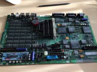
Is the logic Board a Backlit or a Non-backlit model?

 
Last edited by a moderator:

unity

Well-known member
Pic of mobo would help to determine which model. But if you google for images, you can see the difference also. If its a demo unit it should be a non-backlit. This is confirmed by having the upgrade kit cable.


Ferrix97

Well-known member
Great!

How do I turn it on?

Tried hooking my benchtop supply to the main battery and a good 9V battery, but no signs of life

what does the switch on the side do?


unity

Well-known member
Which switches? There are three!

You have the programmer/reset switches on the side. Then you have the battery swap switch sort buried in the back. When the battery cover is removed, it switches power to the 9v so you can swap the battery without losing settings.

The thing is, the Portable is sensitive to amperage and voltage. Even though it a 6 volt cell, you may want to bump it up to 6.5/7 volt. You do not need the 9v since it only works when the switch is up. So supply power at battery terminals (2 amp should work) and push that switch in.

Then try pressing ad holding both the programer/reset switches a few times. Then the space bar to boot. This works for me to get them going.

Odds are though, you need a re-cap of the mobo. I am sending mine out next week to Uniserver for that service since a clean working board is so rare.


Ferrix97

Well-known member
Thanks!,

So is it just like a PB100?, but near the two interrupt/reset buttons, there is also a slide switch with an arrow and a circle, what does it do?

Yup, Ordering caps soon!

tonight I will try again and see what happens!

 
Top