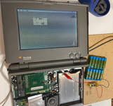
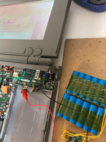
benanderson89 Posted August 21, 2020 Report Share Posted August 21, 2020 (edited) I've done a recap of both the analogue and logic board in a Macintosh Classic. Triple checked all the capacitor values and orientations and they're fine. First time switching it on I heard the speaker crackle into life, but there was no chime. The speaker after a few seconds tried to make noise, like the first fraction of a second of the boot chime being repeated, and then the monitor rapidly started turning off and on with the speaker noise, but I turned it off quickly as it kept on centring the beam after each attempt to create a dot on screen, and I don't want to damage the phosphor. Any subsequent attempts you hear the speaker crackle and the fan spin up, but nothing else. I'm assuming the weird behaviour is because there is no PRAM battery installed. Google hasn't been much help but it seems like erratic behaviour/no-boot is linked directly to the lack of battery. If this is the case, what value and size do I need? Just to double check for the sake of through trouble shooting: 1) no battery is installed 2) no hard disk is installed 3) no keyboard or mouse is connected 4) floppy drive is installed but there is no disk inserted 5) daughter ram board is inserted but I'm unsure if it's working Any help would be fantastic! Thank You. Edited August 21, 2020 by benanderson89 Quote Link to post Share on other sites
erichelgeson Posted August 21, 2020 Report Share Posted August 21, 2020 9 hours ago, benanderson89 said: I'm assuming the weird behaviour is because there is no PRAM battery installed. I have no PRAM batteries in any of my 9" macs and all boot fine (sans accurate time - only Mac I know of that is picky about the PRAM battery and booting is the 6100 series. It sounds more like unstable voltage at first glance - do you have a multi meter you can check it with? If you tested the analog board without load it may be unstable with - so check it at the floppy port with load. Quote Link to post Share on other sites
benanderson89 Posted August 21, 2020 Author Report Share Posted August 21, 2020 Found some wire and measured from the floppy port. Stable voltage (from what I can tell as it was hard to get good purchase on the wires) The 5v was only outputting about 4v. The 12v was slightly under 10v. Massively under-voltage. I hope the freak-out when I first plugged it in was just a fluke, else I might've blown something up! Is there an adjustment pot somewhere on the board? Maybe it just needs a tweek to go with the new caps. Quote Link to post Share on other sites
erichelgeson Posted August 21, 2020 Report Share Posted August 21, 2020 8 hours ago, benanderson89 said: Is there an adjustment pot somewhere on the board? Yes, my classic isn't open right now but it's right in the middle of the board - use a plastic or wooden tool to adjust. I had to do this as well on mine after recapping. I think the one of the old books has a photo/location, let me look. Quote Link to post Share on other sites
LaPorta Posted August 21, 2020 Report Share Posted August 21, 2020 Pina’s Classic & SE book had that location. Quote Link to post Share on other sites
benanderson89 Posted August 21, 2020 Author Report Share Posted August 21, 2020 8 hours ago, LaPorta said: Pina’s Classic & SE book had that location. Have a link? Quote Link to post Share on other sites
erichelgeson Posted August 21, 2020 Report Share Posted August 21, 2020 http://www.maccaps.com/MacCaps/Repair_books_files/Mac Classic %26 SE Repair and Upgrade Secrets.pdf See Chapter 9 Location: PP1 Quote Link to post Share on other sites
benanderson89 Posted August 21, 2020 Author Report Share Posted August 21, 2020 Thank you! I'll head to my parent's place tomorrow and steal my dad's electricians screwdrivers to do the adjustment. All of mine are metal AND magnetic so that's a bit too unsafe for my liking. Quote Link to post Share on other sites
bibilit Posted August 21, 2020 Report Share Posted August 21, 2020 Adjusting PP1 is not safe. You can have a try, but if voltages are not close from 5 and 12 volts, probably something else is wrong. Quote Link to post Share on other sites
benanderson89 Posted August 21, 2020 Author Report Share Posted August 21, 2020 (edited) Anything else I could potentially look at before trying PP1? EDIT: I found a Reddit post with similar super low voltage issues. For him it turns out it was a diode located at DP6. Others suggested he check resistors as well before he found the bad diode. I dug out the Engrish manual to my cheap multimeter and it has a diode test mode, so I'll give that a look tomorrow. I'll take a look at the resistors on the power input side of things, too. Edited August 21, 2020 by benanderson89 Quote Link to post Share on other sites
karrots Posted August 21, 2020 Report Share Posted August 21, 2020 Basically you need to go through all of chapters 8 and 9 of the previously linked book. It will give a rundown of what to check and what to replace if certain conditions are met. Quote Link to post Share on other sites
erichelgeson Posted August 21, 2020 Report Share Posted August 21, 2020 8 hours ago, bibilit said: Adjusting PP1 is not safe. Why is that? I've the book (though of course old) specifically says to adjust it. Just wondering as I did adjust it Quote Link to post Share on other sites
benanderson89 Posted August 21, 2020 Author Report Share Posted August 21, 2020 Brilliant! I'll get on that tomorrow. Quote Link to post Share on other sites
bibilit Posted August 21, 2020 Report Share Posted August 21, 2020 PP1 can be used for fine adjustment only. Been there many times, PP1 will crank one rail safely, but not the other. You will end with 13 volts or above trying to reach the 5 volt figure. The Optoisolator is known to go bad on this situation. Quote Link to post Share on other sites
benanderson89 Posted August 22, 2020 Author Report Share Posted August 22, 2020 My meter has a proper diode test mode according to the Engrish manual. Diode 7 has died. Shows a read out of 040 and the continuity beep sounds. In contrast, Diode 7 on my spare Rev A board reads 335. So I guess I'm buying a new diode! May as well buy a new optoisolator, too, regardless if the one currently on-board works or not. What's an appropriate diode value? Quote Link to post Share on other sites
karrots Posted August 22, 2020 Report Share Posted August 22, 2020 Based on another forum post it looks like the original is an EPG30D which is still available. Attached is a BOM I've used on my Mac Classic and Classic II analog boards. The BOM should be importable into Digikey or Mouser easily. https://forums.macrumors.com/threads/the-little-classic-that-could-nt.1821376/ Bom_8316215 (1).csv Quote Link to post Share on other sites
benanderson89 Posted August 22, 2020 Author Report Share Posted August 22, 2020 That's fantastic! I'll get that ordered ASAP. Mouser and Digikey want £12,00 postage fees if my order is below £33, so I'll be going on eBay instead. Haha Quote Link to post Share on other sites
dochilli Posted August 22, 2020 Report Share Posted August 22, 2020 Classic AB have some other parts that often fail: DP4, DP3, TDA4605, CNY17G-3 Quote Link to post Share on other sites
benanderson89 Posted August 23, 2020 Author Report Share Posted August 23, 2020 (edited) Tested CNY17G-3 and that appears to be working perfectly: for those that don't know, diode test mode across pins one and two, with one being the anode. Then 20kO resistance test across four and five. With TDA4605, all pins (except pin 2, which I believe is by design) have resistance to ground (pin 4), so I'm confident I don't need a new switching chip, either. DP3 and DP4 also register correctly. I'm glad I have my dead Rev A board here because the cathode of DP3 is under a mountain of hot glue and I needed to find a spot to test without having to remove the board from the chassis and it's vinyl insulation pad -- Pin 5 of OP1 is what you need. So it looks like the only component I'm having issues with (that is a known, common problem) is Diode 7. I'll head over to eBay and see about ordering a couple of those now. I was going to use the diode off of my spare Rev A board, but once removed I saw how dirty, bent and corroded the legs were (the battery explosion in that machine really did kill everything). Plus, I don't really want to be replacing a dead 30 year old diode with a probably-dying 30 year old diode. EDIT: Meh, went to mouser anyway. Extortionate shipping for a tiny box of caps (£12,00!) but I need new caps for my IIci anyway, so I may as well buy them all in one on go, plus a spare optoisolator to keep in a parts stash. Edited August 23, 2020 by benanderson89 Quote Link to post Share on other sites
Daniël Oosterhuis Posted August 23, 2020 Report Share Posted August 23, 2020 15 hours ago, benanderson89 said: EDIT: Meh, went to mouser anyway. Extortionate shipping for a tiny box of caps (£12,00!) but I need new caps for my IIci anyway, so I may as well buy them all in one on go, plus a spare optoisolator to keep in a parts stash. Mouser makes more sense in Europe if you buy in bulk. I tend to order when I have several machines worth of caps, as over $50 or so shipping is free. You do need to pay import duties, but Mouser offers DDP, where you pay the duties at checkout, which saves the extra fees that would otherwise be slapped on top of that. And then it's not too bad, really. Quote Link to post Share on other sites
karrots Posted August 23, 2020 Report Share Posted August 23, 2020 I should note my BOM export only works for the 603-0525 Analog board. Model number as printed on the board. The 063-0395 board is slightly different in the capacitor values and locations. Most work. I'll post that list shortly. Quote Link to post Share on other sites
benanderson89 Posted August 24, 2020 Author Report Share Posted August 24, 2020 Ive already got the caps on mine (Rev B, 240v). You should also clearly mark what voltage your BOM is for, too, since there's technically four: A 120, A 240, B 120 and B 240. Quote Link to post Share on other sites
karrots Posted August 24, 2020 Report Share Posted August 24, 2020 Pretty sure for the board that BOM is for the only difference is minus 1x 220uf 250v cap (due to JP1 being in place for 220v) and swap the other 220uf 250v for a 400v version. At least based on comparing my list to recapamac.com.au's board. Similarly, Console5's list for the older boards it has similar variation except both 400v caps exist because JP1 is not under the second cap. I'll add that to the title if I export it to a Google sheet. One other thing to note not related to caps. The optoisolator is a 400mil (10.16mm) version. Finding sockets for this wide that don't require a quantity purchase is a little harder than the standard 7.62mm wide DIP-6. For US buyers Digikey seems to only carry one requiring 1000 min purchase. Mouser seems to have none. Quote Link to post Share on other sites
benanderson89 Posted August 26, 2020 Author Report Share Posted August 26, 2020 (edited) I've just removed DP7 from my Analogue board and tested it completely out of circuit. It works fine! Then I found continuity between the two holes where DP7 used to be. I have a dead short to ground somewhere! The Diode was a complete red herring. I took a photo and marked off (in orange) any pad that triggered the continuity test to the ground pin on the IEC connector and/or the chassis. Every pin on the transformer makes me think it's shorting inside. Any help? I'm loosing my mind looking at this. Edited August 26, 2020 by benanderson89 Quote Link to post Share on other sites
benanderson89 Posted August 26, 2020 Author Report Share Posted August 26, 2020 Completely stumped. I removed the analogue board from the machine, disconnecting the yoke and anode cap (it wasn't connected to the motherboard with the previous test). The cathode end of where DP7 used to be no longer has continuity to ground. I haven't done anything except... remove the board from the case. The power pin on the Molex connector for the hard disk no longer has continuity to ground, too. I also didn't realise that a good number of the pins I had marked as referenced to ground were supposed to be reference to ground. Sorry about that. Guess I panicked and just tested ALL THE THINGS. So I don't know what I did but it seems to have fixed it. I'll reassemble, test continuity again, solder in the new diode and see where I get. Quote Link to post Share on other sites
Recommended Posts
Join the conversation
You can post now and register later. If you have an account, sign in now to post with your account.