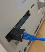
Bunsen Posted May 27, 2020 Report Share Posted May 27, 2020 Quote the black cable tie thing That's called a "grommet" in English, ich hab kein Idee auf Deutsch, schade Quote Link to post Share on other sites
Bunsen Posted May 27, 2020 Report Share Posted May 27, 2020 What other machines would this adapter be compatible with? ie, use the same pinout as the Q900 & 950? Quote Link to post Share on other sites
BadGoldEagle Posted June 1, 2020 Author Report Share Posted June 1, 2020 Hallo Bunsen Thanks a lot for pointing out what it's called. The documentation will look a lot more professional now. Zur Info, diese Dinge heißt 'ne Durchführungstülle. En Français (I'm a french dude living in Germany after all...), ça s'appelle un oeillet ou bien un passe-fil... And yes, this mod is only compatible with Quadra 900/950s as they are (AFAIK) the only Macs with a 24 pin Molex Mini Jr (ATX motherboard) connector. In other news, I've had to scrap the previous fan designs (they weren't compatible with high wattage fans and wouldn't work with all PSUs...). It's now fully PWM and has a thermistor for fan control. A LED lights up once the thermistor reaches a temperature of 80°C/176F. It's still work in progress but it's lookin' good! Quote Link to post Share on other sites
ktkm Posted June 1, 2020 Report Share Posted June 1, 2020 Good looking schematics! (to at least a laymen like myself). Your revitalizing work with the Quadra 900/950 PSU makes me want to pursue my quest for a Quadra 9XX even harder than before! Thank you! Quote Link to post Share on other sites
BadGoldEagle Posted June 11, 2020 Author Report Share Posted June 11, 2020 (edited) I've had to revise the fan controller bit again... Big thanks to the guys over at eevblog.com for their help. Although this still hasn't been 100% approved/verified, it's looking pretty good now! We've mostly redesigned the LED controller circuit - Now we won't be frying op amps with voltages that are too high at the inputs (updated R8 and Vcc for U1). - I've switched to an LM393 (U1)as this is a proper comparator. The 358 wasn't. - Inverting Schmitt Trigger built-in (R5, R6, R11, R12). LED will light up at 84°C and will turn off at 79°C. Just like your engine waring light, it should never light up. If it turns red, please stop carefully and contact your nearest service center (i.e. me). FYI If you don't want temperature control just remove TH1 and replace it with a 10k resistor. If you don't want the Overheating indicator circuit, just leave R5, R6, R8, R9, R11, R12, U1, Q3 and D1 out... this is not recommended but the fan will still work without it. Leave those components out at your own risk. Edit/PS: I'll probably buy a bench supply and a breadboard to test this circuit before I send the boards to production... Edited June 11, 2020 by BadGoldEagle Quote Link to post Share on other sites
mietek Posted June 24, 2020 Report Share Posted June 24, 2020 How’s it going? Sign me up for two sets. Quote Link to post Share on other sites
Ton Posted June 24, 2020 Report Share Posted June 24, 2020 So, 2 weeks ago I've acquired a Quadra 950 Workgroup Server 95 and happy as a clam with the thing. I managed to score 8x4meg parity SIMMs on German eBay, which I plugged in impatiently. Well, you can guess the final outcome. A poof, a small mushroom cloud and some searches later I end up in this post. Truly awesome work @BadGoldEagle! And I'm really curious to the current status of things as I'd very much be interested in a way to get her running again. Quote Link to post Share on other sites
BadGoldEagle Posted June 24, 2020 Author Report Share Posted June 24, 2020 @mietek sure thing... and that makes 10! Now, unless someone wants to buy 5 more, I'll stop the "pre-order" here. @Ton I feel your pain. It was pretty much the same thing for me but instead of RAM that was with the DOS card. And the damn PSU also tried to kill me (to be honest it was probably my fault). I'm really starting to think there aren't any original working PSUs left... And now, for the less fun part. A couple of weeks ago while casually browsing the web, I noticed that the MIC502 supplies aren't as high as I initially thought. I'll have to rethink the fan controller yet again (only for the 5th time). This on top of other life related issues, Apple ditching intel (which in itself almost caused me to fall into a depression), lead me to pause this project for a bit. I need to sort out the life stuff first, but when I'll get back to it (hopefully in the next couple of weeks), I'll most probably pay someone to design the new circuit for me. I just can't handle another failure emotionally. This time, I'd like to use a 555 PWM generator type of circuit, but I can't figure out which one (there's at least 4 different variants) to choose. I'd like it to be still temperature controlled, and to have a minimum speed threshold (duty cycle) of about 40% so that the fan can't possibly stall. More to follow... Quote Link to post Share on other sites
Ton Posted June 27, 2020 Report Share Posted June 27, 2020 So, I've opened the Quadra's case and power supply. The latter looked OK-ish, but on the motherboard something caught my attention. So, the first repair job is on the list. Question; would I need to replace all of them, or will replacing the one that blew be enough? Also; why did this one blow up? Wouldn't want to mindlessly replace this one only for it to be blown up again the next time. Quote Link to post Share on other sites
BadGoldEagle Posted June 27, 2020 Author Report Share Posted June 27, 2020 (edited) When you're dealing with tantalum caps, only replace the ones that are damaged. The rest of them (for now at least) are ok. I don't remember on top of my head what value that cap was and my 950 is currently buried under a pile of stuff... Maybe someone else can help? I think your PSU is what blew that cap. Edited June 27, 2020 by BadGoldEagle Quote Link to post Share on other sites
mietek Posted June 27, 2020 Report Share Posted June 27, 2020 Here’s the same area from one of my Q950s. Quote Link to post Share on other sites
BadGoldEagle Posted June 27, 2020 Author Report Share Posted June 27, 2020 Thanks @mietek 22uF, 16V. Casing is probably C or D. Quote Link to post Share on other sites
olliec420 Posted July 1, 2020 Report Share Posted July 1, 2020 On 6/26/2020 at 11:42 PM, Ton said: So, I've opened the Quadra's case and power supply. The latter looked OK-ish, but on the motherboard something caught my attention. So, the first repair job is on the list. Question; would I need to replace all of them, or will replacing the one that blew be enough? Also; why did this one blow up? Wouldn't want to mindlessly replace this one only for it to be blown up again the next time. So I had the same thing happen to one I just got in the mail. Please see my threads... You should find these helpful. I was able to see the remnants of markings on my burnt cap and was able to determine it was this: https://www.ebay.com/itm/10pcs-T491C106K016AT-KEMET-Tantalum-Capacitor-16V-10-10UF-SURFACE-MOUNT/313012284846?ssPageName=STRK%3AMEBIDX%3AIT&_trksid=p2060353.m2749.l2649 I ordered it and soldiering station but I have not replaced it yet. I did retrobright the plastic pieces of the case and they came out really good. Putting out a blog/video series on it which I will post here and r/vintageapple when complete. Hopefully its done this month or next. As far as BadGoldEagle's PSUs, I would really like to get one but I THINK mine is working fine. I spoke with someone who is electrical engineer who does not think my PSU blew it. I hope he is right. Please let me know how you repair goes and I will you too! Quote Link to post Share on other sites
olliec420 Posted July 1, 2020 Report Share Posted July 1, 2020 On 4/30/2020 at 7:54 AM, BadGoldEagle said: New pictures! Final checks are still in progress... but the new AC board design is now much "safer". BGE: Sorry, I haven't been following this thread closely as I should have been. Are you offering to sell PSUs or the parts and instructions for us to mod our PSUs? Quote Link to post Share on other sites
BadGoldEagle Posted July 1, 2020 Author Report Share Posted July 1, 2020 @olliec420 Parts. 8 bucks would be a little too cheap for a complete mod... those boards will be BIG. Instructions/files will be free once I finish it. Hopefully I'll have a new schematic ready next week. Quote Link to post Share on other sites
olliec420 Posted July 2, 2020 Report Share Posted July 2, 2020 On 7/1/2020 at 5:05 AM, BadGoldEagle said: @olliec420 Parts. 8 bucks would be a little too cheap for a complete mod... those boards will be BIG. Instructions/files will be free once I finish it. Hopefully I'll have a new schematic ready next week. Ahh ok very cool. I definitely want a parts kit too when available. Thanks for all the hard work to keep these old beasts alive! Quote Link to post Share on other sites
BadGoldEagle Posted July 2, 2020 Author Report Share Posted July 2, 2020 The real hard work would have been trying to fix these old beasts, not gutting them... but at least, like Geekdot said, it’ll run cooler, be more reliable and easily repairable in the future... Quote Link to post Share on other sites
Ton Posted July 10, 2020 Report Share Posted July 10, 2020 (edited) OK, update on the AWS95. It lives! It was literally just a replacement of the blown cap and it booted straight up. Well, prior to that I did also wash the complete board with vinegar and rinsed it off with water. This I should have done immediately, as there was some corrosion visible on the board here and there. But the PSU is perfectly fine, the whole machine runs quite stable, although I haven't actually used it for a prolonged period yet. IMG_5492.m4v Edited July 10, 2020 by Ton Quote Link to post Share on other sites
BadGoldEagle Posted July 11, 2020 Author Report Share Posted July 11, 2020 (edited) Great to hear @Ton but given that the engineer I talked to before deciding to do this mod repairs PSUs for a living and tests them at full load for 24 hours before calling them fixed, I wouldn't declare victory just yet... My recapped PSU died during a small stress/smoke test. My plan was to leave it on idling for 3 or 4 of hours but it didn't even pass the two hour mark... But your problem is interesting: it means that computers of this era (early 90s) are starting to suffer from tantalum cap failures. Instead of leaking like the electrolytic ones do, those just explode. ________________________ And now, back to the subject at hand. I have once again decided to change the fan controller (this will be the last time, as I'm sure this will work this time). I just can't get enough from the 555 to do everything it want it to do. I'll now be using an Arduino Nano board (it costs from 1 to 7 bucks depending on who you're getting it from... even clones from China should do the job). I chose it because: 1/ It comes in a PDIP like package. Either solder it to the QuadrATX DC board or install it in a socket. You don't need a hot air station... 2/ It's configurable, because it'll be running a bespoke sketch (read program). If I mess up the code, I can still change it without having to alter the DC board. 3/ It's REALLY easy to flash. Get the free Arduino App for your Mac/Linux/PC, open it, plug in the Nano with a USB cable and hit upload. ANYONE CAN DO IT. 4/ If it dies, there's plenty more available 5/ It's easy to program for and it's got quite a sizable community. 6/ The fan controller part of the schematic is now a lot easier to understand and the circuit won't take as much space on the DC Board as it used to. 7/ Isn't that enough? More to follow... Edited July 11, 2020 by BadGoldEagle Quote Link to post Share on other sites
olliec420 Posted July 11, 2020 Report Share Posted July 11, 2020 On 7/10/2020 at 10:22 AM, Ton said: OK, update on the AWS95. It lives! It was literally just a replacement of the blown cap and it booted straight up. Well, prior to that I did also wash the complete board with vinegar and rinsed it off with water. This I should have done immediately, as there was some corrosion visible on the board here and there. But the PSU is perfectly fine, the whole machine runs quite stable, although I haven't actually used it for a prolonged period yet. IMG_5492.m4v How difficult was the surgery? I have it all ready for me but I just haven't felt the urge to sit and tackle it yet. Ive watched enough videos, I think I got a plan but I am not very experience with this kind of soldering. I got to get this done one weekend soon. Any tip or suggestions for me? Quote Link to post Share on other sites
BadGoldEagle Posted July 12, 2020 Author Report Share Posted July 12, 2020 I don't mean to sound rude but wouldn't this conversation be more appropriate in a PM? In other news, I've decided to use an ATTiny85 instead of the Nano. The boards will come with a preprogrammed chip and I'll offer programming services after the original run of boards is sold out (if there is enough demand outside of the 68kmla, I'll order a new batch of 10). A set will now cost $10 but you won't have to buy the controller so in the end things will be cheaper for you guys. This will reduce board clutter as well. The ATTiny85 is a DIP8 IC while the nano takes about as much space as a DIP30 chip (which does not exist, so I would have had to use a DIP32 socket for the Nano and things wouldn't have been aligned...) Current fan controller schematic: NB1: The relay bit is still entirely optional. NB2: The pot will be replaced by a trimmer. It'll be about $3-4 cheaper. NB3: The LED indicator circuit will probably change as I don't think a single 20mA LED will be bright enough to be seen through the vents at the back (it will be on only if something goes wrong, otherwise it'll be off). The rest of the schematic shouldn't change much now. How this works: - Pins 3 and 7 are the inputs: The pot (pin 3) will allow the user to set the minimum fan speed (lowest position=50% and highest=100%). Pin 7 has the thermistor which will make the fan speed up/down linearly as the temperature increases/decreases. Still haven't decided on what the curve should look like. Should the max. temperature be lowered to 75C? Only actual testing will tell. - Pins 5 and 6 are outputs. Pin 5 will go straight to a MOSFET, which in turn will modulate the fan's ground and therefore its speed. Pin 6 will be used for the LED indicator circuit. Now on to write software for the thing! I'll code this for Arduinos 'cos that's just easier. Quote Link to post Share on other sites
ktkm Posted July 12, 2020 Report Share Posted July 12, 2020 8 hours ago, BadGoldEagle said: I don't mean to sound rude but wouldn't this conversation be more appropriate in a PM? I like to follow this thread Quote Link to post Share on other sites
BadGoldEagle Posted July 19, 2020 Author Report Share Posted July 19, 2020 Hi all Small update... I have received most of the parts I need to test the fan controller circuitry. Unfortunately the ones I don't have (the MOSFET and the pots) are pretty critical and I can't calibrate my controller until I get hold of them. But at least I got the "programmer" ready... And I tested my "bench" 12V PSU with the Noctua and the original Sanyo.... Interestingly enough, even though the Sanyo is older and noisier, it moves A LOT more air compared to the Industrial PPC Noctua... But the latter should still be plenty enough as the Becker PSU doesn't really need any cooling (it has massive heatsinks!) and the fan MOSFET won't generate much heat (according to my calculations, the max. temperature rise in the worst case scenario will be 3°C (1A fan), or about 1.5°C for the Sanyo, negligible!) Here's the current version of the microcode: // QuadrATX fan speed controller // // The Apple Chronicles // // v0.25A // // NOTES: // set board to 8MHz!!! // configure Arduino as ISP // CALIBRATION NEEDED, currently using dummy values. // variables declaration int SensorPin = PB2; // pin 7 int PWMPin = PB0; // pin 5 int PotPin = PB4; // pin 3 int LEDPin = PB1; // pin 6 int SpeedPin = PB3 // pin 2 int SensorVal; // "temperature" from NTC int PWMVal; // fan PWM output "speed" int PotVal; // real potentiometer value, to define the cold/normal operation fan speed. int PotValmapped; // lowest position shall correspond to the absolute minimum speed (see below) and not OFF, new potentiometer value int MinSpeed=64; // absolute minimum speed, 0=0% and 255=100%, currently set to 25%, corresponds to lowest pot value // Calibration variables, TBD int NTCcold=450; // corresponds to ambient temperature, 10K for a 10k NTC @25°C int NTChot=800; // corresponds to highest temperature before LED lights up, about 1.3K for a 10k NTC @80°C int PotMin=0; // corresponds to lowest position on potentiometer int PotMax=800; // corresponds to highest position on potentiometer // setup code, to run once void setup() { // set PWM frequency of PB0 (Pin 5, ATTiny85, fan output) to 31,250 Hz. TCCR0B = TCCR0B & 0b11111000 | 0b001; // define pin modes ATTiny85 pinMode(SensorPin, INPUT); pinMode(PotPin, INPUT); pinMode(PWMPin, OUTPUT); pinMode(LEDPin, OUTPUT); pinMode(SpeedPin, OUTPUT); // Set fan to full speed for one second at startup (prevents stall) analogWrite(PWMPin, 255); delay(1000); } // main code, to run repeatedly void loop() { //read NTC sensor value SensorVal = analogRead(SensorPin); if(SensorVal < NTCcold){ // in case ambient temperature is lower than 25°C SensorVal = NTCcold;} //read pot value PotVal = analogRead(PotPin); // map and assign pot/pwm values. 0 to 255 corresponds to 0 to 100% PotValmapped = map(PotVal, PotMin, PotMax, MinSpeed, 254) // change potentiometer characteristic, lowest position corresponds to absolute minimum speed PWMVal = map(SensorVal, NTCcold, NTChot, PotValmapped, 255); // linear fan curve from ambient to LED lighting up. PotValmapped is the minimum fan speed set by the potentiometer // Overheating indicator if (SensorVal>NTChot){ PWMVal=255; // full speed analogWrite(LEDPin, HIGH); // LED ON } else { analogWrite(LEDPin, LOW); // LED OFF } //write the PWM value to the pwm output pin analogWrite(PWMPin, PWMVal); //basic RPM indicator analogWrite(SpeedPin, PWMVal); } I added a basic RPM indicator at the last minute... hopefully that'll work. For debug purposes only... Comments/suggestions are welcome. I also updated the schematic. It's not final (I'll probably place the MOSFET horizontally and the traces are most certainly too thick): Quote Link to post Share on other sites
BadGoldEagle Posted July 19, 2020 Author Report Share Posted July 19, 2020 Just realized while performing a quick verify/compile that I forgot a couple of semicolons... I remember back when I was a freshman at university, our coding teacher used to subtract one point from our grade (out of a max. of twenty) per missing semicolon. Ah those were the days... Also: Sketch uses 1290 bytes (15%) of program storage space. Maximum is 8192 bytes. Global variables use 13 bytes (2%) of dynamic memory, leaving 499 bytes for local variables. Maximum is 512 bytes. Nice! So ATTiny25s and ATTiny45s can also be used without an issue (as long as they're of the PU aka PDIP variety). Quote Link to post Share on other sites
Ton Posted July 19, 2020 Report Share Posted July 19, 2020 I'll keep following this topic as I'm interested in eventually replacing the power supply, even though mine seems good now (I've since installed A/UX fully). Quote Link to post Share on other sites
Recommended Posts
Join the conversation
You can post now and register later. If you have an account, sign in now to post with your account.