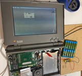
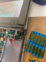
bibilit Posted April 24, 2017 Report Share Posted April 24, 2017 All is said, usually those boards are blowing fuses because the Mosfet is bad, i replaced the mosfet (shorted) and caps and the analog board blowed the fuse immediately, destroying the new Mosfet at the same time. So the problem is elsewhere... any idea ? Quote Link to post Share on other sites
360alaska Posted April 24, 2017 Report Share Posted April 24, 2017 FLYBACK Likely shorted. Quote Link to post Share on other sites
techknight Posted April 24, 2017 Report Share Posted April 24, 2017 (edited) Ummm... no. Replace the PWM IC. its a TEA or TDA something. I forget which one. When you lose the MOSFET, you lose the driver IC with it. just about every time. Edited April 24, 2017 by techknight Quote Link to post Share on other sites
bibilit Posted April 24, 2017 Author Report Share Posted April 24, 2017 TDA 4605 maybe ? Quote Link to post Share on other sites
techknight Posted April 24, 2017 Report Share Posted April 24, 2017 (edited) Sounds right. it connects directly to the MOSFET. Also if there is a resistor or diode between the MOSFET and the IC, those need checked/replaced as well. Edited April 24, 2017 by techknight Quote Link to post Share on other sites
360alaska Posted April 24, 2017 Report Share Posted April 24, 2017 (edited) Isn't this mosfet connected to the flyback transformer primary? Not saying your wrong, just asking. Edited April 24, 2017 by 360alaska Quote Link to post Share on other sites
techknight Posted April 24, 2017 Report Share Posted April 24, 2017 (edited) No it isnt. I think the flyback has a BU408 but I cant recall. it is almost always an NPN transistor. its in the main power supply. Which technically could be called "Flyback" but for very different reasons, and its not the flyback your thinking of Edited April 24, 2017 by techknight Quote Link to post Share on other sites
BadGoldEagle Posted April 24, 2017 Report Share Posted April 24, 2017 No it isnt. I think the flyback has a BU408 but I cant recall. IIRC, it's a BU-406. Close enough though! Quote Link to post Share on other sites
360alaska Posted April 24, 2017 Report Share Posted April 24, 2017 (edited) Yeah, I guess I was going off this schematic that someone made: I have both versions of classic analog boards and neither have a "BU406" . Edited April 24, 2017 by 360alaska Quote Link to post Share on other sites
techknight Posted April 24, 2017 Report Share Posted April 24, 2017 (edited) huh... go figure. First time I have EVER seen a mosfet used in the primary of the LOPT circuit. But, at the same time, that circuit design doesnt have a horizontal driver transformer coupling, so its operating in voltage mode instead of current mode so I guess that would be a necessity there. But its an IRF640 anyways, not the same as the IRFBC40. I have seen the IRF640 used in car audio amplifiers, and I mean a ton of them. Still made today. Edited April 24, 2017 by techknight Quote Link to post Share on other sites
360alaska Posted April 25, 2017 Report Share Posted April 25, 2017 Oh, my bad... Quote Link to post Share on other sites
Ferrix97 Posted April 25, 2017 Report Share Posted April 25, 2017 Usually when the mosfet blows, there are a few more components that fail with it, sometimes it's the regulator IC (but quite rare), and most of the times is a fusible resistor (can't recall value or location, possibly between the IC an the gate of the mosfet) and a polyester (blue or yellow) capacitor that's also close to the mosfet. Will try and dig up more information later if needed. Quote Link to post Share on other sites
bibilit Posted April 25, 2017 Author Report Share Posted April 25, 2017 Will try and dig up more information later if needed. yes i appreciate. Quote Link to post Share on other sites
Ferrix97 Posted April 25, 2017 Report Share Posted April 25, 2017 I'm away from home, so don't have a classic AB in front of me. Looking at my notes, the capacitor is CP23 (270pf 2000V) and the resistor is RP40 (220 Ohms Fusible). Both of them are very close to the mosfet. You should also check for shorted diodes (mainly the two big rectifiers, but doesn't hurt to check all of them) Quote Link to post Share on other sites
Mc128k Posted April 25, 2017 Report Share Posted April 25, 2017 Also try to trace all components from the power plug to the transformer primary coil. I'm not an expert on this, but I suppose that if the power mosfet gets toasted every time maybe it's because it's drawing too much current, and that could be because it's not oscillating. Try to backtrace the gate driver, and debug that part of the circuit. Quote Link to post Share on other sites
bibilit Posted April 25, 2017 Author Report Share Posted April 25, 2017 Thanks, Diodes were ok, removed from the board and tested fine. will have a look at the resistor. TDA 4605 can be tested ? Quote Link to post Share on other sites
Ferrix97 Posted April 25, 2017 Report Share Posted April 25, 2017 usually a bad TDA won't drive the mosfet, so it would show no life. You can compare it with a good working board my monitoring the supply voltage (pin 6) when slowly ramping up the mains voltage with a variac. but if yours blows the mosfet, that shouldn't help. Check the board for shorts or burnt resistors, but there's a high chance that the capacitor I mentioned earlier (even if it measures ok) is bad, I've seen that kill mosfets before. Quote Link to post Share on other sites
techknight Posted April 25, 2017 Report Share Posted April 25, 2017 (edited) the TDA4605 will indeed blow the MOSFET if the chip is shorted internally. So it will drive full chip VCC into the MOSFET Gate putting it into full saturation which will make the FET go KERPLOW! Which it blows the fuse instead. I am not too familiar with the Classic design, but I know power supplies and have rebuilt enough power supplies on various things to fill a house, and I know this to be fact... Usually when a mosfet fails, it fails shorted through all 3 legs. Back to Gate. the microsecond it happens, it can send 160VDC B+ back into the drive pin of the chip just before it pops the fuse or causes other things to fail. if there is a Source resistor, and it opens, it will literally drive 160VDC B+ into the Drive pin all the time... But it usually wont pop the fuse. The fact that it keeps shorting the FET and popping the fuse, tells me the circuit path is complete on the Drain and Source pins. Usually if there are passive components between the TDA and the Gate of the MOSFET, it will take those out. Sometimes... But not always. Easiest way to rule the IC out is to leave the MOSFET out, and replace the fuse. Turn on the machine, and do a voltage check at the drive pin of the IC. if its pegged at VCC then yep... Otherwise, scope it and make sure the drive signal is within tolerance. But experience tells me rule of thumb, when you change the MOSFET that suffered in the event of failure, you change its drive electronics too! Given all of this, I still cannot rule out the possibility of the oscillator not running. if the oscillator doesnt run, and the state is pulled high, it can mimic the same thing assuming the small chance the drive IC is still good. These days when I design electronics that need switching control, I usually try and capacitively-couple the output stage to the drive electronics with the appropriate pull-ups/pull-downs so in the event of oscillator failure or the loss of a specific regulated B supply, it doesn't blow the whole machine sky high. Edited April 25, 2017 by techknight Quote Link to post Share on other sites
bibilit Posted April 26, 2017 Author Report Share Posted April 26, 2017 Thanks for all this information. So, correct me if i am wrong, TDA 4605 is receiving supply voltage at pin 6 (as Ferrix advised) and delivering output to the Mosfet gate through pin 5. Quote Link to post Share on other sites
techknight Posted April 26, 2017 Report Share Posted April 26, 2017 (edited) yes as well as having built-in circuitry for dead-time control, under-voltage/over-voltage/over-current lockout, and the oscillator. Edited April 26, 2017 by techknight Quote Link to post Share on other sites
bibilit Posted April 27, 2017 Author Report Share Posted April 27, 2017 Ok, many thanks, from the information collected, supply voltage should be around 10 volts ? Quote Link to post Share on other sites
Ferrix97 Posted April 27, 2017 Report Share Posted April 27, 2017 Yes, there's a slight dip at around 9V when the IC starts working (if you measure while connected to a variac). But before staring to measure the IC, I'll change the poly cap and the fusible resistor first Quote Link to post Share on other sites
bibilit Posted April 28, 2017 Author Report Share Posted April 28, 2017 Ok, thanks, will order parts this week, don't have any spare except for the TDA4605. Quote Link to post Share on other sites
Recommended Posts
Join the conversation
You can post now and register later. If you have an account, sign in now to post with your account.