• Hello MLAers! We've re-enabled auto-approval for accounts. If you are still waiting on account approval, please check this thread for more information.

The Color Classic LCD Project.

pizzigri

6502
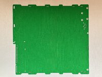
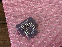
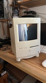
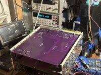
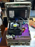
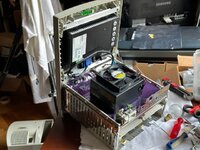
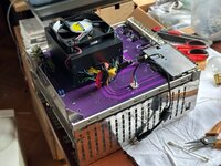
So, what the title says. I have a so-so working Color Classic, that has been upgraded in a lot of ways. It uses a 575 board, with 64MB RAM, an Apple CS1 network card, full 040, Defor's ColorFusion LC PDS video card, BlueSCSI v2, and floppy gear upgrade.
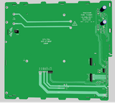
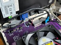
The Analog board was modded to display 640x480, VGA mod, and completely recapped/replaced some components, like the ultra hot Zeners, RIFA cap, etc - the works.
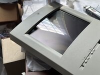
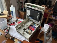
So, this beauty starts giving me occasional video problems - the image would be unstable, then it would go back being excellent etc. I other threads, and replies I got, it seems the flyback is at fault. It's the only part that is irreplaceable. The frigging trinitron tube this machine employs was built for two specific uses: as a Medical machine monitor, and color monitor for television studios cameras. Therefore NO replacements can be found. I could not find a used Analog Board, I've kept the WTB post here for a long time and been on the lookout for weeks and no joy - but i found a second complete Color Classic.
So I got this crazy idea. Rebuild the logic board hoping that the second CC has a good FBT, and use it to build a fully stock and collector grade Color Classic, with original LB, tube resolution of 512x348, etc etc.
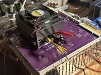
And build a second one with all the bells and whistles of the Mystic upgrade BUT with a completely redesigned "analog board", using a standard ATX/SFX PSU with soft power, MUCH better audio, and a 8.4" LCD display.
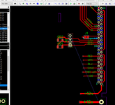
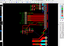
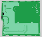
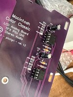
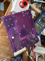
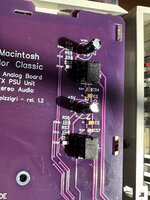
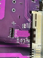
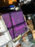
The new AB would be a PCB housing the original connector for the CC harness, routing the power rails from the PSU, placing the original AC socket and power switch at the correct spot on the rear bucket and circuits on it would include a stereo audio amp, RGB and SYNC signal routing to an internal VGA connector (or something like that), sense line setting for the two resolutions that the VGA mod originally devised for the Takky/Mystic provided (640x480 60hz and 800x600 56hz).
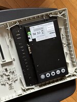
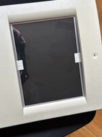
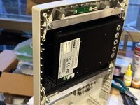
Incidentally, I got my hands on a "NIB" GVision K08AS 8.4" monitor/Industrial LCD that IS exactly 8.4" with VGA analog input. Already got it and I am happy to say that it works perfectly with the 68K macs I have (LC475, Quadra 700), at both resolutions, 640x480 and the native 800x600 that are relevant to the CC. Nice thing, I tested it at the oddball 800x600 @56hz, and it works fantastically, although reporting 60hz... here is the Ebay BIN for 29 euro: https://www.ebay.it/itm/312807856587 (no connection to the seller).
As soon as I receive the "parts" CC, I will sell from it a few things at Forum friendly prices, just to recoup some funds to fuel my project - namely the CRT, LB, floppy, and what else I will not be using for this build.
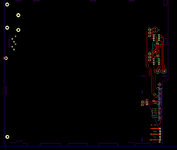
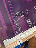
I intend to design in Diptrace the full PCB with the same footprint as the original AB, and if everything works, I will post the Gerbers and BOM - I will also have at least three boards to give out as i will only need the one to place in my CC. This is the intention, and I will update as soon as I get some materials and info.
 
So a little update, seeing as there was a similar thread on the SE30 (https://68kmla.org/bb/index.php?threads/fun-with-colour-on-my-se-30.32723/): the idea is the same, my problem is also dying unobtanium parts in the CRT drive/analog board - and in no way related to “improving” the CC, otherwise the easy path is to place a G4 mini (like 50 euro on second hand markets) and cheap lcd monitor in the emptied housing.
The whole point would be to preserve as much as possible the original machine and find a way to make it work at 512x384 with the original logic board. But this is a second step, as I already have a 8.4” - and there is definitely a long term idea in using flexible oled displays that would take the exact curve of the cc bezel to recreate the exact experience of the original machine - costs are too high at present though, at over 400 euro.
I am at this point debating if I should simply reuse the analog board stripped of all EHT and CRT drive circuits, preserving audio, power rails etc, or redesign the logic board as initially considered.
 
I might suggest to start with getting hold of a CC wiring harness and trying to come up with some kind of lashup based on it that will let you run the CC LB etc outside of the case, with a third party PSU and some kind of video scaler. After that, worry about fitting it all in the case.
 
Hey @cheesestraws, yup that’s the idea! Matter of fact, I am tracing out the various signals to route on the replacement analog board. Which I have started drafting, using the dimensions and positions of the necessary parts which needs to be recovered from a non functional AB such as the connector (any idea if it actually is available ), the rear metal bracket holding the AC plug and switch, the fan connectors etc. on top of this pcb I will place a stereo audio amp (1-3w or so) and an SFX psu. here is my progress so far.
 

Attachments

  • IMG_1327.jpeg
    IMG_1327.jpeg
    4.8 MB · Views: 129
The PCB basic draft I made can be used for a lot of Color Classic projects and hacks, I used Diptrace if anyone os wondering. The SCX PSU is needed not only to supply yhe computer, but the LCD display as well - it needs a good 12v, 2A supply so I decided that drafting from scratch could be easiest.
 
So with this update, I do NEED some help. It may be even trivial - so, I'm drafting the AB to be able to support a daughter PSU (essentially, a standard SFX pcb and ancillaruy bolted on a with all rails connected to it). I see two leads coming from the main AB connector, one is ADB the other is Power off. How do I use these to soft power on and off the Color Classic? Can I reuse the trick i already used for the PSU rebuild of the Quadra 700 PSU and the 6300 PSU? How toconnect these leads and where....?

the rest I am figuring out, at least for the moment... I rebuilt the CC audio circuit using the TDA7052A because this way i retain the volume control buttons and the audio control panel in the OS. I just remade it to be stereo. Chips are not terribly expensive or hard to find on the bay.
 

Attachments

  • PCB-27-7.png
    PCB-27-7.png
    12.8 KB · Views: 81
  • PCB-27-7DETAIL.png
    PCB-27-7DETAIL.png
    23.3 KB · Views: 66
Adding soft power circuit, shamelessly copying GeorgeRudolf's OldMacATX design (thank you George).
Still having some indecision to what goes where due to everyone using different labels for the various connections.
The layout is very obviously a work in progress... once done, I'll publish all gerbers etc
 

Attachments

  • PCB-28-7.png
    PCB-28-7.png
    56.1 KB · Views: 66
Progress, I have identified about 98% of all pins and connections, although I'd love to have someone go through my draft and tell me if I made obvious mistakes... this is the board as it looks in the 3D tool.
I am using a 300W SilverStone SST-ST30SF as a SFX PSU daughterboard , which should work reasonably well for a Quadra 700, so it should also work for a Color Classic. Of course, a 12v 2A tap is also needed to power the chosen LCD, an old stock NIB 8.4" detailed in my first post. Can any one have mercy and look at the board?
 

Attachments

  • sopra.png
    sopra.png
    83.1 KB · Views: 57
  • sotto.png
    sotto.png
    31 KB · Views: 86
Tested fit of the LCD in the front faceplate of the Color Classic. No modification at all on the CC, I modeled the lcd case instead. The screen still has all protection on as I have not finished .
 

Attachments

  • IMG_1536.jpeg
    IMG_1536.jpeg
    1.7 MB · Views: 93
  • IMG_1537.jpeg
    IMG_1537.jpeg
    1.5 MB · Views: 107
Again some updates. The LCD is mounted to the front of the CC, I used a 0.75mm Plexigas sheet to simulate the curved front of a Trinitron display. I mounted it using 3M superstrong tape, and also added rounded top and bottom fillers to avoid ungainly empty spaces behind the plexiglas - nothing is glued and can be easily returned to stock - not that it would be possible, since the AB I had is shot anyway. The impression is amazing.
Also I found an interesting way to control it using the front holes, I built a small board with the 5 buttons to control the LCD and placed it right behind the front grille holes, so the buttons are reachable via a paper clip. Not more is needed, once set I really do not use the monitor controls all that much anyway, but it sure beats having to open the CC case every time. AB board replacement is done, I'm waiting for the fab to deliver. in any case, here are some pics.
 

Attachments

  • IMG_1686.jpeg
    IMG_1686.jpeg
    1.9 MB · Views: 86
  • 65CFF06E-893A-4E37-A2AA-85FB692E7A9B.jpeg
    65CFF06E-893A-4E37-A2AA-85FB692E7A9B.jpeg
    657.4 KB · Views: 82
  • IMG_1569.jpeg
    IMG_1569.jpeg
    1.7 MB · Views: 84
  • IMG_1567.jpeg
    IMG_1567.jpeg
    2.1 MB · Views: 96
Hey thanks! Really appreciate it.well got to say that the boards I’m waiting are v2.0 - I made a few mistakes and actually thought about a few improvements in the meanwhile so I’ve got 5 boards to throw away. Bah
in any case they were invaluable to check all mechanical dimensions and stuff!
 

Attachments

  • IMG_1709.jpeg
    IMG_1709.jpeg
    2.7 MB · Views: 96
  • IMG_1710.jpeg
    IMG_1710.jpeg
    2.3 MB · Views: 97
Ok, so I received the “final’ pcb and assembled the thing. Mechanically in lines up perfectly. I tested the Psu with the LCD as minimum load and jumpstarted as detailed on the psu instructions (green lead to gnd). The psu starts and all rails work, with correct voltages. However, when I connected the logic board, and tasted the soft power on, it would start to shut down immediately after. I suspected a short, but it does not look like it as with the LB out and my pcb inserted in the harness, I can measure good voltages across the HD Molex, and where they are expected (5v on red, 12v on yellow)….
i also tried bypassing the soft start by jumpstarting, exactly as in fist functionality test above. Nothing, and swapping the 575 board with a CC gave me a different response : half of a deathchime and then a red light went off inside the psu! Disconnected everything of course, however I cannot fathom where the problem is, any suggestions?
 
Some photos
 

Attachments

  • IMG_2128.jpeg
    IMG_2128.jpeg
    332.2 KB · Views: 65
  • IMG_2127.jpeg
    IMG_2127.jpeg
    357.9 KB · Views: 55
  • IMG_2126.jpeg
    IMG_2126.jpeg
    383.3 KB · Views: 54
  • IMG_2125.jpeg
    IMG_2125.jpeg
    372 KB · Views: 57
  • IMG_2124.jpeg
    IMG_2124.jpeg
    373.2 KB · Views: 56
  • IMG_2123.jpeg
    IMG_2123.jpeg
    352.5 KB · Views: 65
Some more.
 

Attachments

  • IMG_2141.jpeg
    IMG_2141.jpeg
    121.5 KB · Views: 67
  • IMG_2140.jpeg
    IMG_2140.jpeg
    130.3 KB · Views: 70
  • IMG_2139.jpeg
    IMG_2139.jpeg
    131.3 KB · Views: 67
  • IMG_2138.jpeg
    IMG_2138.jpeg
    141 KB · Views: 72
  • IMG_2137.jpeg
    IMG_2137.jpeg
    130.6 KB · Views: 68
You've got some good stuff here. That's a nice trick with the plexiglass.

Pretty unusual that the PSU would have any kind of light inside of it, but assuming it's a power LED and the PSU shut down of its own volition (while PS_ON was still jumped to ground) that implies protection circuit of some sort was triggered. Overcurrent (short) would be most likely cause.

Do you see the appropriate voltages at the appropriate points on the LB connector?
 
Yeah, I'd look at the voltages on the rails *while the computer is attempting to run*. I wonder if the PSU you're using goes a bit funny if the load on 5 and 12V lines aren't balanced the way it expects - I had one a while ago that wouldn't run without extra load on the 12V line, but the voltages looked fine unloaded.
 
OK I'll check, in the meanwhile I'm posting the Gerber files for the whole project up to now for anyone that wants to check them out and maybe see some obvious error! And also obviously - these gerbers are not final, at least until i manage to make the whole thing work, but it is my intention to disclose the whole thing at the end so that anyone else interested can make their own LCD CC....
If anyone wants to take a look, you're welcome!

BTW, the small PCB for the button I/F and the Zuluscsi sled adapter work just fine...
 

Attachments

Yeah, I'd look at the voltages on the rails *while the computer is attempting to run*. I wonder if the PSU you're using goes a bit funny if the load on 5 and 12V lines aren't balanced the way it expects - I had one a while ago that wouldn't run without extra load on the 12V line, but the voltages looked fine unloaded.
That's a good point. Cheap group regulated power supplies do not like it when you pull one rail heavily and weird stuff can happen. You can test out of the machine by using a bunch of lightbulbs or even resistors to put 5 amps or so of load on the 5v rail of the PSU.

Also, what model of PSU is it? Sometimes you can find reviews or manufacturer specs that will tell you.
 
Hey Joe,
it's actually a good PSU, a SilverStone ST30SF... what I am doing now is trying to resurrect the broken analog board to measure and trace things. The EHT FBT was toast, so I removed it, removed the transistor, and the CRT harness - see pic; it should beable to supply the basic voltages to the LB this way and not be dangerous. Actually, the portion I need is the larger one, in the second photo the more orange transformer is the switching supplying the 5 and 12v rails (and the -12), VSB etc. The smaller one is the one giving out 64v for the CRT.
I'll trace all that goes to the connector and see if someone at the PCC (Power Color Classic) made some mistakes. I mean, there's a 7905 that apparently goes to pin 1, and on the PCC site that is labeled -12v, and I need to measure it, but a 7905 gives out -5v, not -12. We'll see.
 

Attachments

  • IMG_2153.jpeg
    IMG_2153.jpeg
    424 KB · Views: 56
  • IMG_2154.jpeg
    IMG_2154.jpeg
    400.9 KB · Views: 51
Back
Top