• Hello MLAers! We've re-enabled auto-approval for accounts. If you are still waiting on account approval, please check this thread for more information.

SE/30 with multiple issues

Greetings from a newcomer to 68kMLA. I have an SE/30 from 1989 that I'd like to restore to full operation, but it has a number of issues:

• can only boot from a System 7 floppy – the hard drive doesn't appear, and neither Disk First Aid nor HD Setup can find it

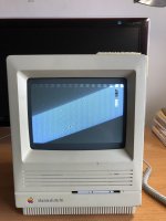
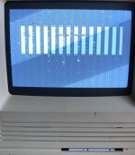
• display is distorted with broken vertical lines and gaps that make screen information hard to read

• the boot disk is stuck in the floppy drive – doesn't eject upon shutdown, and inserting a paper clip through the little hole won't dislodge it

I know that I'm going to have to open the case, but I'm not sure what to do after that. I have no computer repair experience apart from installing SIMMs in PowerBooks.

I'll be grateful for any guidance about where to begin. I've downloaded Classic Mac Repair Notes as recommended below, and I have a PDF copy of The Dead Mac Scrolls. Thanks...
 
Welcome to the forum!

You'll need a couple of things if you're going to get your SE/30 fully working again. The main ones are time and patience.

Those books are good, but there are more modern resources available now, mainly YouTube.

Garbled video/display (can we see a photo of the symptoms please?) could be caused by bad capacitors, or there may be another problem. To start with, you want to recap the logic board - that means removing the old electrolytic capacitors and replacing them with new ones (or with a different type of capacitor, like tantalums which won't leak over time). There are some good videos about soldering here if you're new to it:


The floppy drive will need to be fully disassembled/restored. They are prone to getting stuck once the original grease has worn out. The floppy read/write head will also need cleaning. There is a good video on how to do this here:


I wouldn't worry about this right now, at least not until the logic board has been recapped. But you can replace the original hard drive with an SD card based device, much more reliable and silent! The popular choices are either a SCSI2SD or BlueSCSI. Where you get those depends on what country you're in, there are resellers around the globe for both. BlueSCSI is the cheaper choice.

A photo of the logic board in your machine would be useful to see, just in case we can identify anything else that might be wrong with it.

I'll finish with a word of warning - if you've never opened an SE/30 before, you need to be mindful of two things: there's high voltage stuff going on in there, even after its been switched off. You don't need to discharge the CRT if you're not going to touch anything relating to the CRT or analog board, so you just need to be mindful of not touching that stuff. Thankfully, you don't have to touch any of that to remove the logic board.

Secondly, when removing the logic board, sometimes people yank too hard on the logic board power connector/cable and in doing so, they hit their hand against the CRT yoke/yoke board which, depending on how hard the impact is, can permanently damage the CRT. Be gentle with removing the power cable from the logic board and you should be fine.

In terms of how to remove the logic board, instructions are in this guide:


Hope that helps. Let us know how you get on.
 
What a detailed, awesome first response post!

A hearty welcome here as well. I will chime in with just a few suggestions:

1. Recap of everything needed as already suggested. The video line issue can be due also to leaking capacitor goop interrupting traces too and from other video circuitry chips (I’ve seen it described before…but figuring out what is not my specialty). I’d look for corrosion on the pins of chips near to the surface mount capacitors first. If you are new to or not skilled at surface mount component, I’d either practice on a scrap board or consider outsourcing the work.

2. Get that PRAM battery out of there ASAP before it blows! They are prone to doing so with age, and if yours hasent, then you are very lucky thus far.

3. With the aforementioned removal of the analog board to logic board connector, opinions may differ, but if you are afraid to whack the yoke board with your hand, I would suggest taking off the yoke board first as it leaves more clearance for your hand.
 
As mentioned above, if this is your first soldering project DON’T start out on your Mac! Get something common, mass produced, cheap, and that nobody cares about to practice on first. Broken DVD players, clock radios, or or WiFi routers are good candidates.

Or just let somebody who already knows what they’re doing fix your Mac.

Also as mentioned above, that CRT is more fragile than one would expect; especially the neck. Be very careful removing the circuit board that’s on the neck. Also, I would discharge the anode just to be on the safe side. Yes, there is a ‘bleeder’ resistor that’s supposed to do that automatically, but if it’s not working right and your hand brushes the wrong part while a charge remains you could be in for a rather unpleasant experience (and as your arm jerks from the shock, you could break the CRT that you’ve been trying so hard not to). Also, if you get hit just wrong, or have a heart condition, the shock could be fatal; so being safe rather than sorry is a good idea here! It’s easy to do and takes about two seconds; those PDF guides you’ve got will have a section on how to do it.
 
If you have a battery that’s leaked, you’ll want to use a diluted solution of white distilled vinegar first to neutralize the alkaline fluid; and then baking soda in water to neutralize the vinegar; followed by a thorough rinse with water, and then spray it with isopropyl alcohol to help clean any oils left and promote drying. Be sure to use distilled water; any minerals dissolved in tap water can leave a residue that can be somewhat conductive. After cleaning, be sure to let the board dry for several days before applying any power to it: moisture and electrical power combine to produce corrosion as well as short voltage to places it shouldn’t be. You can, however, solder on it while it’s slightly damp; just dry the area you’re working on with a paper towel first.

The same general procedure applies for capacitor leaks.
 
As for soldering equipment; first you’ll need a proper temperature controlled soldering station (not just a power setting - it should have a thermostat in it that you can set to a specific temperature). I’m partial to stations that take T12 style integrated tip/heater cartridges because they are more responsive and keep the tip at-temperature better. As for which tip to use, generally bigger is better; as there’s more surface area in contact to transfer heat and the larger body of the tip conducts the heat from the heater better. I use a ‘hoof’ style tip for almost everything, but a ‘screwdriver’ or ‘chisel’ tip works nicely also (these are so named because that’s what they look like).

Some people use a special style of damp sponge to clean the tip as they are working, but I prefer the dry brass style (looks like a scrubber for pots and pans).

Be sure to use good electronics-grade 63/37 leaded solder, and plenty of flux. Never use solder for plumbing, as the flux in that stuff is quite corrosive to PCBs and components. “No-clean” style of flux and solder is preferred, as it’s not corrosive (however, cleaning it off after you’re done is a good idea just because it’s sticky). I use “Chip-Quik” brand paste flux in a syringe, because it cleans up with 99% isopropyl alcohol nicely, but there are other good brands also (Amtech comes to mind, but again, there are others too). Don’t bother with 70% isopropyl; the 30% water in it means that the flux won’t dissolve in it - it’s quite hydrophobic.

Good tweezers are a must, as is some sort of pick or probe tool (such as a dentist might use).

Electrostatic discharge precautions are also a must. Get a kit with a mat (ESD-Safe silicone is preferred because of it’s heat tolerance; it won’t melt and burn if you accidentally drop the iron on it); wrist strap; and grounding cable (and make sure that the safety resistor in the kit is present: with a multimeter on resistance mode, check that there’s about 1 to 5 mega ohms between the wrist strap and the end of the cable that attaches to your ground point, be that the grounded box, screw, or terminal on a convenient power outlet, or a metal water pipe, etc - if somehow you manage to brush up against something with mains voltage on it, that resistor will keep large amounts of current from flowing, but it’s still conducive enough to drain static charges from your body in a reasonable amount of time). These kits can be had on Amazon, eBay, Banggood, and other online sellers; and aren’t very expensive either. I picked up another small one a few weeks ago, and yesterday I spent more $$$ at Taco Bell for lunch for myself and my dad than I did on the kit.
 
Fume extraction of some sort is important. An open window with a fan, or any of the dedicated soldering fume absorbers (made from a fan with an activated carbon filter attached) will work. You won’t breathe lead or other metal vapors because soldering temperatures are nowhere near what it takes to vaporize those metals, but the smoke from the flux burning off (and any plastics that you accidentally bump with the iron) is rather nasty. However, you will get lead on your hands and make lots of little tiny balls of loose solder as you are working, so a through hand-washing, cotton gloves if you can, and general cleaning of your workspace afterwards are a must… especially if there are kids or pets around. If your workspace is over carpet; I would put down something to catch any stray solder balls before they work their way into the fibers (newspaper, perhaps… just don’t slip on it!).
 
Welcome to the forum!

You'll need a couple of things if you're going to get your SE/30 fully working again. The main ones are time and patience.

Those books are good, but there are more modern resources available now, mainly YouTube.

Garbled video/display (can we see a photo of the symptoms please?) could be caused by bad capacitors, or there may be another problem. To start with, you want to recap the logic board - that means removing the old electrolytic capacitors and replacing them with new ones (or with a different type of capacitor, like tantalums which won't leak over time). There are some good videos about soldering here if you're new to it:


The floppy drive will need to be fully disassembled/restored. They are prone to getting stuck once the original grease has worn out. The floppy read/write head will also need cleaning. There is a good video on how to do this here:


I wouldn't worry about this right now, at least not until the logic board has been recapped. But you can replace the original hard drive with an SD card based device, much more reliable and silent! The popular choices are either a SCSI2SD or BlueSCSI. Where you get those depends on what country you're in, there are resellers around the globe for both. BlueSCSI is the cheaper choice.

A photo of the logic board in your machine would be useful to see, just in case we can identify anything else that might be wrong with it.

I'll finish with a word of warning - if you've never opened an SE/30 before, you need to be mindful of two things: there's high voltage stuff going on in there, even after its been switched off. You don't need to discharge the CRT if you're not going to touch anything relating to the CRT or analog board, so you just need to be mindful of not touching that stuff. Thankfully, you don't have to touch any of that to remove the logic board.

Secondly, when removing the logic board, sometimes people yank too hard on the logic board power connector/cable and in doing so, they hit their hand against the CRT yoke/yoke board which, depending on how hard the impact is, can permanently damage the CRT. Be gentle with removing the power cable from the logic board and you should be fine.

In terms of how to remove the logic board, instructions are in this guide:


Hope that helps. Let us know how you get on.
joshc, thanks so much to you and everyone else in this thread for the awesome advice. A coupe of shots of the display are attached. It looks like I have my work cut out for me – should be an adventure!
 

Attachments

  • IMG_1382.JPG
    IMG_1382.JPG
    1.8 MB · Views: 20
  • IMG_1387.jpg
    IMG_1387.jpg
    1.4 MB · Views: 19
OK, I know from those photos what is going on, but I’ll have to refer to the SE/30 schematics to come up with a list of possible reasons why.

Basically every other 16 pixels of the video memory is not getting written to by the CPU; which on this machine means two bytes of VRAM… and here I’m temporarily stuck because PG&E is replacing a utility pole and is due (overdue, actually) to cut off the power here any second, so my iMac (where the cleaned-up/redrawn schematics and apps to read them are) is turned off. I’m posting from an iPad right now. I should have more guesses later on this evening after they turn the go-juce back on.
 
Initial guess: I think it's UC8; and that pin 4 of that chip is being interpreted by the chip as always high; causing all writes to the first 16 bits of a row to go to the next 16 bits; leaving the first 16 bits uninitialized, resulting in the stripes of garbage data you are seeing.

I am suspecting that it's the chip itself at this point, because I would think that holding A2 of the address bus high due to a short would cause the machine to immediatally crash (it's showing signs of having booted correctly, but having a video problem). Likewise, if the output line from UC8 to the VRAM chips was what was affected, you would get a different display issue (instead of garbage in the first 16 bits, you would get mirrors of bits on screen).
@bdurbrow, thanks very much for this. I now know that I have VRAM issues in addition to everything else. I appreciate everyone's offering a helping hand to a noob.
 
I don't think it's the VRAM chips themselves; because you would have a different pattern showing on the screen if that were the case.
 
The schematics indicate that the line in question (A2) is common to all the other devices on the board that have an address bus connection. If the trace for A2 were being pulled up by contamination; the machine would not boot. This implies that pin 4 of UC8 may be corroded or the trace leading to pin 4 of UC8 may be corroded thru, along with enough voltage leakage due to contamination to cause pin 4 to float high.
 
Back
Top