
Sorry if this is the wrong section for a general question. I didn't know where else to put it.
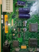
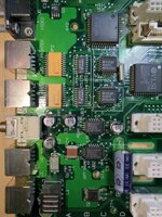
So, this is my first post, and it's about my first shot at repairing anything. I'm working up to doing my first recap and repair, on a IIci. It's... Pretty much the bog standard issue.
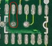
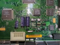 I've already cleaned this up a bit, and did some prodding for continuity. Haven't been able to find any breaks so far. So it's not as bad as it looks. Neither is the damage in the audio/serial section. Maybe I'll find a problem later on, but it looks like this is going to be straightforward so far.
That's the context. So on to the question:
I'm building a BOM for the repair, and I ran into an issue... Its an issue I'm sure everyone is running into, but I can't find anyone talking about it.
How are people derating 47u capacitors on a 12v rail? Because I'm struggling to find a 25v that fits.
My original plan was just to buy a bunch of 25v solid caps and put them on all the 47u, just for simplicity's sake... But that went right out of the window when I went looking for them.
I'm looking on Mouser, and as far as I can see... Tantalums in a C package cap out at 20v, Polymer-tantalums in the same package caps out at 10v. You can get 25 volts in a D package easily, but they'd overshoot the pads. Meaning, at best, you have to solder them on the underside, and they'll be floating above the board.
Aluminum Organic Polymer caps seemed ideal for a moment... They come in the same kind of cans as the originals, and are apparently pretty good. ...But apparently not for an audio circuit. The ESR is too low, and they have too high voltage leakage. This is a problem, because +/-12v is on the audio.
I then saw someone talking about hybrid caps. Aluminum Organic Polymers with a small amount of juice in them. Apparently, they have far lower DC leakage. But the ESR is still kinda low, and they can still leak.
So I guess what I'm asking, is... What is everyone using to derate? Are they cramming the D size caps in there, or are they using 20v tantalums? Or did I just miss something?
So, this is my first post, and it's about my first shot at repairing anything. I'm working up to doing my first recap and repair, on a IIci. It's... Pretty much the bog standard issue.
I've already cleaned this up a bit, and did some prodding for continuity. Haven't been able to find any breaks so far. So it's not as bad as it looks. Neither is the damage in the audio/serial section. Maybe I'll find a problem later on, but it looks like this is going to be straightforward so far.That's the context. So on to the question:
I'm building a BOM for the repair, and I ran into an issue... Its an issue I'm sure everyone is running into, but I can't find anyone talking about it.
How are people derating 47u capacitors on a 12v rail? Because I'm struggling to find a 25v that fits.
My original plan was just to buy a bunch of 25v solid caps and put them on all the 47u, just for simplicity's sake... But that went right out of the window when I went looking for them.
I'm looking on Mouser, and as far as I can see... Tantalums in a C package cap out at 20v, Polymer-tantalums in the same package caps out at 10v. You can get 25 volts in a D package easily, but they'd overshoot the pads. Meaning, at best, you have to solder them on the underside, and they'll be floating above the board.
Aluminum Organic Polymer caps seemed ideal for a moment... They come in the same kind of cans as the originals, and are apparently pretty good. ...But apparently not for an audio circuit. The ESR is too low, and they have too high voltage leakage. This is a problem, because +/-12v is on the audio.
I then saw someone talking about hybrid caps. Aluminum Organic Polymers with a small amount of juice in them. Apparently, they have far lower DC leakage. But the ESR is still kinda low, and they can still leak.
So I guess what I'm asking, is... What is everyone using to derate? Are they cramming the D size caps in there, or are they using 20v tantalums? Or did I just miss something?