Hi All,
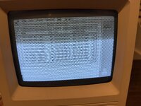
I have recently picked up a Mac SE/30 that boots fine but has a horrible wavy horizontal picture distortion as per attached pic.
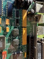
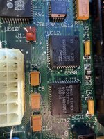
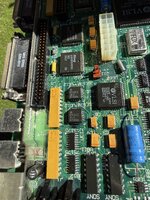
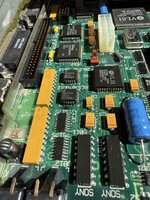
The unit has been recapped and I tested the board in a known good machine with the same result which makes me thing it's a motherboard issue.
I did give it a good clean in IPA but same result.
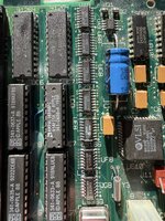
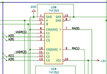
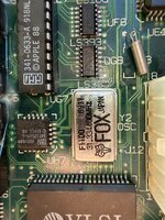
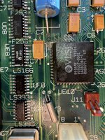
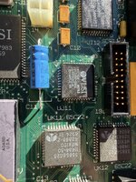
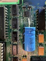
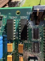
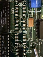
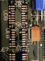
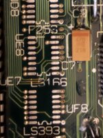
I've also attached a p[hoto of the U8 area which apparently is notorious for causing failures as I can't see any issues.
Any help/advice appreciated.
Thanks
Sonny
I have recently picked up a Mac SE/30 that boots fine but has a horrible wavy horizontal picture distortion as per attached pic.
The unit has been recapped and I tested the board in a known good machine with the same result which makes me thing it's a motherboard issue.
I did give it a good clean in IPA but same result.
I've also attached a p[hoto of the U8 area which apparently is notorious for causing failures as I can't see any issues.
Any help/advice appreciated.
Thanks
Sonny