• Hello MLAers! We've re-enabled auto-approval for accounts. If you are still waiting on account approval, please check this thread for more information.

Mac Plus that went on fine (only the analog board)

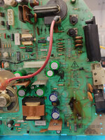
this is the beginning of the repaying of the Mac Plus that went partially on fire

before
1732665080723.png


1732665099132.png
1732665110465.png
how splendid! :D

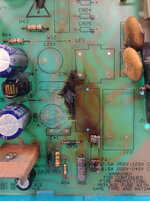
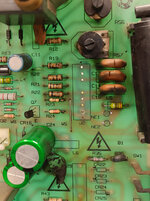
it's better not to be frugal and replace all the darkened resistors, diodes and capacitors.
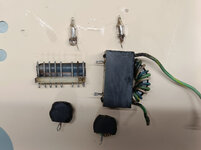
What about inductances... can I measure the H? Or simply replace them all with no mercy?
They are "only" for filtering purposed.. any advice?
 
As a note, you'll want to clean the surface of the board *extremely* carefully (or get one of the new replica boards) - the burnt material is much more conductive than the unburnt material, and there are mains voltages sloshing about down there.
 
I'm browsing for this info, I got the Apple one, but I'm looking for the BOM because the inductors L9 L10 are probably gone and also the transformer, LF1 LF2
It's unclear if the circuit of the reloaded and its BOM correspond to the original Apple board.
I'd like to avoid the reloaded,
 
Hi Ironborn!
Thats a toasty Plus! 😲

Yes, The BOM on my reloaded correspond to the original Apple board (rev 820-0107-D). The board is a 100% replication.
If it is a 110V board some parts will differ.
LF1 and LF2 are linefilters. Probably you will be able to find replacement parts. The footprint will be the most challenging :)
 
Thank you, @daanvdl, and thanks for the PCB recreation.

Could you provide the specifications for the line filter? Would any line filter work? I have some non-functional switching power supplies, and I was thinking of measuring the inductance to ensure a proper fit. Is that the correct approach? How to measure the Henry?

Also, what are the specifications for the L9 and L10 components? They are not shorted but appear to have been damaged by heat.

By the way, is there a specific reason why the SW1 switch was not designed to be positioned higher, closer to the J5 connector?
 
Last edited:
@cheesestraws Ah ahn ... thanks mate. I was underestimating this aspect.

This is one of the big problems with electrical fires: burning things produces carbon, which acts like a resistor, which generates more heat, which burns more stuff, which makes more carbon, which generates more heat, and so on...

I'm browsing for this info, I got the Apple one, but I'm looking for the BOM because the inductors L9 L10 are probably gone and also the transformer, LF1 LF2

This thread has the PSU schematics for the 240V version: https://68kmla.org/bb/index.php?threads/128-512-plus-240-v-psu-schematics.38953/ I did them initially then @michimartini made corrections. The PDF with details on how the bloody thing works is at https://vintageapple.org/gamba2/images/plus_analog.PDF - the theory of operation is the same for the 240V one but the schematics are slightly different because of the voltage difference.

Could you provide the specifications for the line filter? Would any line filter work?

Someone else may correct me here, but I believe that line filters are pretty interchangeable
 
I do measure around 1mH on both lines on the Plus filter (LF2) and around 15mH on both lines on LF1 with my LCR meter.
Let us know if you can find new filters which will fit on the board! :)

I think it’s perfectly fine to deviate slightly in values if you find new suitable components. The original value might be tailored to meet stricter EMC (Electromagnetic Compatibility) requirements.

 
Last edited:
some updates here
the board was cleaned with the magic sponge
LF2 despite the look, is not shorted and it tests 25mH not like the 15mH @daanvdl measured (thanks), but I'll keep it.
LF1 looks terrible but there is no short and it tests 0,4mH and 0,5mH respectively
L10 L6 test 0.2mH, I added a new shrinking tube.

So in the end, I'm going to replace the capacitors, just in case, but the rest seems ok.

But I have an issue with the N1 and N2 that looks like a small thermionic valve: one is fine the other has a pin compromised. They are in the picture attached.
I don't see them in the schematics, what are those? How can I replace it? T
 

Attachments

  • IMG20241208174408.jpg_compressed.JPEG
    IMG20241208174408.jpg_compressed.JPEG
    456.4 KB · Views: 10
  • IMG20241208174413.jpg_compressed.JPEG
    IMG20241208174413.jpg_compressed.JPEG
    438.8 KB · Views: 10
  • IMG20241208174421.jpg_compressed.JPEG
    IMG20241208174421.jpg_compressed.JPEG
    439.5 KB · Views: 12
  • IMG20241208180617.jpg_compressed.JPEG
    IMG20241208180617.jpg_compressed.JPEG
    225.9 KB · Views: 13
what are those for??

overvoltage protection - if the voltage gets higher than the strike voltage of the bulb, the bulb starts to conduct quite enthusiastically and lights up and shorts everything out, protecting the components "behind" it. Quite a clever thing.

 
is there a replacement? or can I simply leave open the one that is broken o should I try to restore the broken pin?

N .. does it stand for neon? :D :D
 
Back
Top