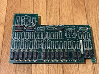
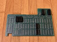
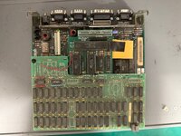
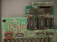
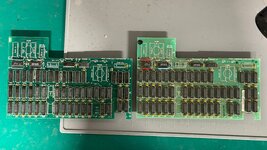
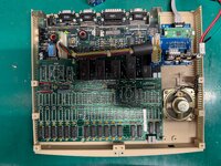
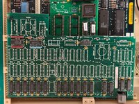
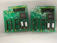
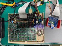
I am restoring a Mac 512K with a 512K Dove MacSnap 5.0 RAM Upgrade card + SCSI.
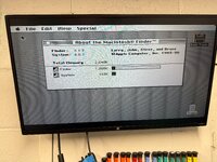
This upgrade card brings the Mac RAM to 1MB.
But I've seen some other Dove MacSnap RAM Upgrade cards that contain 1MB or 2MB of RAM.
Is it possible to upgrade my upgrade card to 1MB or even 2MB?
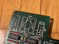
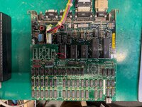
Also, one of the snap connectors is bit corroded, any possibility of getting a new one? Or were those made to order parts just for this upgrade cards?
This upgrade card brings the Mac RAM to 1MB.
But I've seen some other Dove MacSnap RAM Upgrade cards that contain 1MB or 2MB of RAM.
Is it possible to upgrade my upgrade card to 1MB or even 2MB?
Also, one of the snap connectors is bit corroded, any possibility of getting a new one? Or were those made to order parts just for this upgrade cards?
")