Diagnosing Macintosh Classic

Hello forum!

I picked up a non-functional Macintosh Classic (1991) and I would love to know if there is a chance to get this working again. I've never done a repair of this sort before, but I have OK'ish soldering skills. I'm hoping to get some advice from you all as I work through.

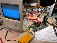
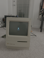
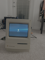
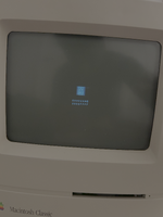
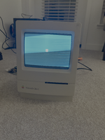
The state of the system when I got it: Powers on but nothing shows up on the screen. The screen itself doesn't seem to be on.
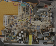
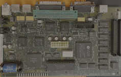
I have opened up the case and pulled out the logic and analog boards (after safely discharging).

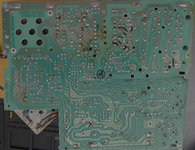
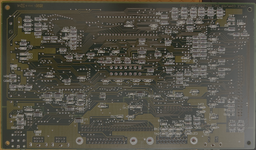
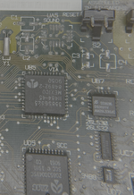
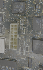
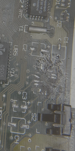
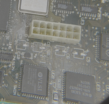
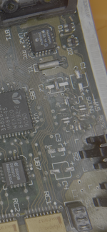
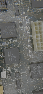
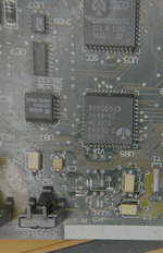
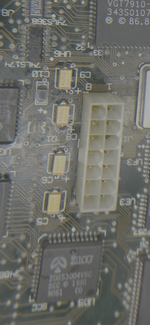
Visually inspecting the boards, I don't see any major corrosion or leakage. Some pins have rust, but for the most part seems OK. On the logic board, the capacitor cans also seemed OK visually.. no obvious signs of leakage. But as soon as I touched one of them, it immediately came off. So did a few other caps. I then removed the rest of them as well. So obviously these need to be replaced. I have ordered the cap kits from Console 5. However, looking at the pads, I cannot tell if they are intact. I tried apply some solder on them and on some of the pads the solder sticks, but for a few pads it doesn't seem to be holding. I'm attaching some images. Would love to hear from an experienced pair of eyes on how things stand.
 

Attachments

  • analog_back_1.png
    analog_back_1.png
    17.1 MB · Views: 33
  • analog_front_1.png
    analog_front_1.png
    16.4 MB · Views: 16
  • logic_back_1.png
    logic_back_1.png
    14.1 MB · Views: 16
  • logic_caps_1.png
    logic_caps_1.png
    3.6 MB · Views: 16
  • logic_caps_2.png
    logic_caps_2.png
    3.7 MB · Views: 18
  • logic_front_1.png
    logic_front_1.png
    13 MB · Views: 26
Cap goo on Classic analogue boards is like honey, it leaks down and dries out causing all sorts of damage along the way. It will need a deep clean before and after recapping Also search here for other likely components you'll need to replace: the optoisolator, and TDA4605 on first thought.

The motherboard looks good, it should come up well with a recap kit.
 
Looking at the back of the analog board I see the telltale signs of rot creeping through the board; those are the "black dots" around some of the through hole components. I see it a lot near the transformer and speaker because the capacitors in that area are terrible. Your board's not too bad looking. As Byrd said, you'll want to have the TDA4605 at IP1, CNY17G at QP1, and some 1N4148 diodes on hand to replace the diodes at DP3 and DP4. I have a stock of all these and I replace them regardless of their alleged condition because Classic/II analog boards are made with junk components.

Regarding the "solder won't stick" observation, I've seen that a lot with these. There's something about the leaking electrolyte that chemically/physically changes old solder so it won't melt under normal heat anymore, and that gives the impression that the pad is gone or that solder won't stick or it just beads up on top of the surface. I've found that flooding the area with a decent blob of solder and gently rubbing/scraping the iron into the pad will eventually transfer enough heat into the solder and the pad to liquify the old solder. The little bit of old gets mixed into the new solder and then you suck/wick away the entire blob, thoroughly clean the area with alcohol/qtips, and repeat until the pads are sparkling or you've accidentally applied too much heat for too long and boiled away the adhesive that held the pad to the PCB. I've done both!

I have pretty good mechanical empathy these days after having done dozens of board cleanings/recaps, plus plenty of Game Gears and the like, and it's something you figure out with either time, luck, or mistakes. Sometimes the pad is already loose and gets ripped off very quickly, and other times I'm scraping away at it, convinced I'm just gouging into the PCB with the soldering iron, but after ten seconds of scraping I finally get through the oxidation and old solder and suddenly the solder is sticking to a small portion of the pad.

My typical course of action is to remove the caps from the motherboard and clean up the pads for new capacitors. I'll pull any socketed ICs or anything removable like RAM, ROM cards, or that odd SCSI terminator on your board (I've never seen one of those in a Classic). If the board is really dusty/filthy/moldy. I'll physically clean it with simple green or a product by Stoner called "Plastic Surface Cleaner," which is the best cleaner I've ever used for plastics. A gentle bristle brush works wonders for cleaning. Next, I'll soak the motherboard in a bag of vinegar for about an hour to neutralize the alkaline capacitor corrosion, then rinse it off under a faucet for a minute or so. An electric air duster at full speed is great to blow as much water out from under the chips as possible. Next, I dribble/pour some distilled water over the board. This helps flush out the tap water. I'll dry under the chips again with the air duster. Finally, I squirt a few ounces of 99% isopropyl alcohol from a chemical squeeze bottle and give the board another good soak: the alcohol absorbs water and flushes it away. One last blow dry and then I put it in front of a fan for an hour or two. After it's sparkling clean, it gets a recap.

If you decide to vinegar soak the analog board also, you'll want to drill the speaker rivets out and remove that since the cone is paper and will be destroyed by soaking. I've shortcutted by layering paper towels on top of the corroded capacitor section and only soaking the area with vinegar, but I've also had some really, really bad boards. I reattach the speaker with two nuts and bolts.

In summary: Your boards look pretty okay but expect a lot of leakage under the big bundle of capacitors on the analog board when you get those off. "While you're in there" replace the diodes and the opto 6-pin IC and voltage controller 8-pin IC. For the logic board, you may feel you're going to "waste" a lot of solder creating the 'bubble" that'll get through the corrosion but you need the surface area and fresh solder for the old stuff to mix into. Some scraping might be required to break through the oxide layer: be firm but gentle. It's a skill you get with experience. Use a vinegar soak to neutralize the cap leakage on the logic board and thoroughly clean/dry the board afterwards.

One final observation: If there's corrosion on the pins of the big connector in the center of the motherboard, check the cable on the analog board that connects to the logic board. I've seen the logic board's cap corrosion work its way up into the plug. If there's green or brown fuzz anywhere, soak the plug and an inch or two of the cable in vinegar also.

I have a billion pictures I've taken of all these steps. If you want clarification of any of the points I've shared, I can probably dig up a visual.
 
thank you Byrd and thank you DJ68K for that comprehensive rundown. Much appreciated. I did an initial cleaning with a toothbrush to remove some of the dust and dirt. I was hoping it would expose the pads a bit more but didn't have much luck. So I guess a thorough clean is in order, which is what I'll try next. I'll be focusing on the logic board first, though I've already ordered the cap kits for both boards. Question: is it possible to 'bring up' or test in any way the logic board separately, i.e. without putting everything back together and powering the whole thing up?
 
Get yourself an ATX extension cable. Only part of it will fit in the harness but it'll let you set the board on the table next to the computer so you can work on it while it's running. It's VERY useful when you're using a logic probe or oscilloscope.
 

Attachments

  • IMG_6178.jpeg
    IMG_6178.jpeg
    1.9 MB · Views: 19
I did some spot cleaning of the capacitor regions on the logic board with 99% isopropyl alcohol and then tried to perform the 'large block of solder, work it into the pads to dislodge the old solder'. There was some success. A couple of pads came out shiny. But a few pads didn't budge no matter how much i tried (e.g. negative pad of C9). The sound chip pads were particularly screwed. I spent the most time on that one and I ended up lifting one of the pads (the one that is crooked in the picture), at which point i decided to stop.

A couple of questions here:
1. Are the capacitor pads looking ok? I'm still not able to get solder to stick well to the 'problem' pads, so i'm not sure what i would even do once i get the cap kits.
2. If the pads are indeed gone, is there a way around?
 

Attachments

  • logic_caps_3.png
    logic_caps_3.png
    2 MB · Views: 6
  • snd_1.png
    snd_1.png
    1.1 MB · Views: 6
It's kind of hard to tell. There seems to be a lot of black goo left on pads, but yeah, that UA5 area looks pretty bad. Soak with IPA (the cleaning fluid, not the beer) and clean well, but gently. Scrape the pads, very gently, with something sharp to get the goop off, if indeed the pads are still there. Fiberglass pencil maybe? I tend to use something like the tip of a sharp box cutter blade, I use a microscope though.

If those pads are gone, then soak yourself in IPA (the beer, not the cleaning fluid) and see if that helps.
 
I'll second SpocksBeer: Once you've "scraped into" the corrosion with a sharp blade, the flux/solder blob/scraping with the iron might work better. I'm seeing the same thing bibilit is that the capacitor pads all look good and usable. I should've mentioned this before: I strongly encourage you to use a multimeter to tone out the pad over to the nearest via and/or wherever the trace eventually ends up to. I've had many frustrating situations where the trace is broken right as it meets the pad and it's not visible. It takes a few extra minutes to do and it's totally worth it when you recap the board and it's not working. It's far easier to find and fix broken traces now than after you've put capacitors on the board.

What I didn't notice before sending my previous wall of text is that one of your pictures showed UA5 (sound chip) was missing; I think I missed it because later pictures in the sequence had the chip in place. That looks very chowdered up, and if I'd seen that I would've expressed more patience in that area. I've solder-blobbed SMD pads before but I move quicker, apply less pressure, and am more careful when using braid to wick the solder away to inspect the quality of the remaining pads underneath. As previous suggested, definitely spend the time to check each pad to whatever via it's supposed to go to here: the sound chip pads are much more fragile than the capacitor pads and more prone to microfractures caused by corrosion.

That said, this still looks very fixable to me: Take good photos of the board with the sound chip missing and use your multimeter to tone out the destination of each damaged/missing leg. Use your multimeter and tone out every pad, every trace. Draw a map on paper if you need to. Once you resolder the chip back to the remaining pads, you can use wire to reconnect the legs of the chip to whatever via or other destination the trace went to. Using your map, once you resolder the chip verify from the top of the chip's legs that each "known good" leg is properly hooked up. For the missing/destroyed pads, run new connections with wire from the chip's leg to wherever they go. I prefer using 30ga insulated kynar wire but others like enameled magnet wire.

If you haven't vinegar-soaked the board yet, I'd recommend letting it marinate for an hour, then cleaning it throughly. The vinegar might help loosen up some of the corrosion.
 
I'll second SpocksBeer: Once you've "scraped into" the corrosion with a sharp blade, the flux/solder blob/scraping with the iron might work better. I'm seeing the same thing bibilit is that the capacitor pads all look good and usable. I should've mentioned this before: I strongly encourage you to use a multimeter to tone out the pad over to the nearest via and/or wherever the trace eventually ends up to. I've had many frustrating situations where the trace is broken right as it meets the pad and it's not visible. It takes a few extra minutes to do and it's totally worth it when you recap the board and it's not working. It's far easier to find and fix broken traces now than after you've put capacitors on the board.
I have been doing the the multimeter check you mentioned actually, and the good news is that i was getting some signal, but not a robust one. I was hoping that after the cleaning + soldering + wicking would make it better, but it doesn't seem to have improved much. Perhaps i'm doing a lousy job at cleaning. I will try the vinegar soak method next.

by the way, would it help if I use flux during the solder+wick stage? I didn't want to erode the board further so i haven't been doing that.
 
What I didn't notice before sending my previous wall of text is that one of your pictures showed UA5 (sound chip) was missing; I think I missed it because later pictures in the sequence had the chip in place. That looks very chowdered up, and if I'd seen that I would've expressed more patience in that area. I've solder-blobbed SMD pads before but I move quicker, apply less pressure, and am more careful when using braid to wick the solder away to inspect the quality of the remaining pads underneath. As previous suggested, definitely spend the time to check each pad to whatever via it's supposed to go to here: the sound chip pads are much more fragile than the capacitor pads and more prone to microfractures caused by corrosion.
This was my bad. The first picture that I took indeed had the sound chip on. When I was removing the caps, this chip just 'floated off'.

Would the system be able to boot without UA5 in place? I do have the dislodged chip saved in my stash for reference, but i'd rather put off replacing this until things start to look rosier with the rest of the system.
 
Back
Top