checklist I used for the audio repair on the classic II rev A board
C3 47uF 16V
- gnd
+ R2, R7, R15
C4 47uF 16V
- phones switch
+ pin 5 U1
C5 10uF 16V
- gnd
+ pin 8 U2 (78L08), R21
C6 10uF 16V
- gnd
+ R6 (4k7 to R15)
C7 10uF 16V
- gnd
+ pin 7 U11 , R33
C8 10uF 16V
- gnd
+ pin 3 U1
C9 1uF 50V
- pin 10 DFAC
+ R29
C10 10uF 16V
- mic in
+ pin 3 U11 , R7
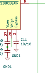
C11 10uF 16V
- gnd
+ pin 2 DFAC
pin 1 DFAC is connected to R32 , R37
C12 10uF 16V
- R35 , U11 pin 6
+ pin 6 DFAC , R40
C13 47uF 16V
- gnd
+ pin 1 U12
C14 10uF 16V
- gnd
+ pin 1 U2 (78L08)
C15 1uF 50V
- pin 12 DFAC
+ pin 13 DFAC , R37
 Hello Guest! We're hosting a challenge to welcome vintage Intel macs to the MLA during the month of July! See this thread for more information.