• Hello MLAers! We've re-enabled auto-approval for accounts. If you are still waiting on account approval, please check this thread for more information.

adding 4mb SGRAM to PowerPC 5500/6500 ... and possible ATi Rage Pro upgrade

pizzigri

6502
So, a few months back I read this post: link by the great Trag, and started researching how to upgrade the stock ATi Rage II based video on my PowerMac 6500 board.
I PM'd Trag and we discussed a bit on the possibility to double the VRAM of the PM 6500, a possibility that would open interesting scenarios.
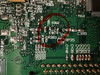
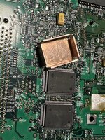
This can be accomplished by replacing the 1mb SGRAM chips on the logic board with 2mb parts - - for a total of 4MB.
So, Jeff graciously sent me a few KM4132G512Q-10 chips, they're 256 X 32 X 2 (2MB) each, while the chips already soldered on the 6500 are MT41LC256K32D4, 128 X 32 X 2 (1MB). I am adding both Data Sheets below.
While the pin for BA, according to the 6500 schematic, is connected (they are both dual bank chips) the caveat here is that address lines A8 and A9 are, for some unfathomable reason, mapped on different pins on the MT and KM memory chips footprint which are otherwise essentially the same.
I will undoubtedly have to bodge some wires to solve this.
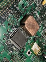
But, studying the data sheets of both memory chips, I realized I needed to know about the Rage II video chip to know where to place those bodges. Yes, the ATi Rage II in the 6500 schematic features pin labels, but I needed to know how the chip worked.
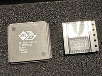
It turns out no data sheet is available anywhere online for the Rage II... but there's a technical reference manual for the Rage Pro! And I found out that, in the PCI compatible, PQFP 208 package implementation, it is a direct, pin to pin compatible part, meant to simplify upgrading existing designs of integrated M/B graphics built around the Rage II.
So, it is possible that it is a drop in upgrade for the 6500 board, adding substantial performance (at least double the acceleration, plus much better 3D games compatibility and much more). Well, let's say that at least, it should equal the video performance of the beige G3, that incidentally uses the Rage pro...
This more or less sums up the research I did, however impossible to do otherwise without Trag's input and help.
 

Attachments

Last edited:
This would be terrific if possible, especially for the 5500! I have a couple spare 5500/6500 boards and I believe I have a junk beige G3 board laying around somewhere. Willing to blindly swap ICs if that helps. :)
 
This would be terrific if possible, especially for the 5500! I have a couple spare 5500/6500 boards and I believe I have a junk beige G3 board laying around somewhere. Willing to blindly swap ICs if that helps. :)
Well, I do not have yet a Rage pro chip yet... if you can salvage one from a broken MB, download the technical reference manual, check all relevant things and give it a try! The reference crystal used in the 6500 is the correct 14.318 MHz, and the stated voltages for the Rage Pro are 3.3V Core, 5V PCI I/O, and 3.3V memory interface. The way I read the 6500 schematic, is that both 3.3 and 5V rails are available for Vcore on the logic board, and presently, on my 275Mhz board it's set at 5V; easily selectable by removing R382 (a R0 SMD jumper) and moving it to the R383 pad. Look at the image.

Edited to add: of course, also PLLVDD and DACVDD need to be 3.3V... not only Vcore. The schematic has these options as well, sorry no photo of the PCB at this time. But look at the schematic I am adding below.
Before doing anything check all voltages. Im also including the 6500 schematic here.
 

Attachments

  • powermac_6500 schematic.pdf
    powermac_6500 schematic.pdf
    3.7 MB · Views: 4
  • IMG_4482.jpeg
    IMG_4482.jpeg
    848.1 KB · Views: 45
  • vcore 6500.png
    vcore 6500.png
    13.4 KB · Views: 16
  • pllvdd.png
    pllvdd.png
    28.1 KB · Views: 10
  • power and gnd pins rage pro.png
    power and gnd pins rage pro.png
    22 KB · Views: 15
Last edited:
So unfortunately I only have a 5500 chassis which makes it prohibitive for testing voltages etc. The plastics are fragile, so I’m not willing to take it apart. I’ll look through my bins to see if I have an extra Gazelle harness.

Edit: Or maybe I can just apply the proper voltages to the power pins? Not sure if any of the other pins in the slot are needed for testing the voltages to the ICs. Should work in theory.
 
Last edited:
Sounds like a good project. What I'd really like to see is some sort of internal CRT mod for the 5500 so can use a PCI video card as primary
 
Just dropping a note in here, I'm interested in this topic and have a 6500 harness without a case for probing/prodding/etc.
I'm currently waiting on parts to arrive, though it'll probably be a couple weeks.
 
I think I have the needed voltages configured for 3.3v(ish) operation. Scrounged some parts from the PCI card I had ordered to fill in the PLLVDD bits for pins 110&115, it was originally sitting at 4.23v but is now down to 3.2v. The RAGE II currently runs with reduced voltages but I haven't stress tested it much to know if stability is affected.

Before I go too far with this I do have a question, however. What is the likelihood of this actually working with the board's current ROM? If this goes on and I'm needing to get into OF every other boot that's gonna suck because this system with a BMOW Wombat has a really difficult time getting the timing right to enter OF.
I'm probably still going to stick it on anyway, but figured I might want to bring that question up. I figure if it doesn't work I just cut it's power and use a PCI Radeon, hopefully that works without crashing when the onboard is disabled.

PXL_20250925_090819087.2.jpgPXL_20250925_094236048.2.jpg

Here are some measured voltages for the sake of taking notes:

*RAGE PRO PCI CARD -no display:
PLLVDD GIO4 115 5v
PLLVDD CS1 110 3.12V
VDDR 3.12V
AVDD 3.09V
VDDC 3.12V
PVDD 3.35V

*6500 BOARD STOCK:
PLLVDD GIO4 115 4.23V
PLLVDD CS1 110 4.23V
VDDR 3.28V
AVDD 5V
VDDC 5V
PVDD 4.74V (LINKED TO AVDD)


*6500 BOARD SWITCHED / (LC Filter populated):
PLLVDD GIO4 115 4.17v (now 3.2v)
PLLVDD CS1 110 4.17v (now 3.2v)
VDDR 3.2v
AVDD 3.2v
VDDC 3.2v
PVDD 3.2v

Not sure about the how or why of pins 110 and 115. On the 6500 they are tied together and on the PCI card they have different voltages... Unless I'm out to lunch and managed to measure the wrong pin, IDK.

Please let me know if you notice anything that seems like bad news.
 
Uhhh that is a rage pro turbo, I only have the tech sheet of the pro - dunno if they are the same thing. Maybe? What’s for sure is that the pro was made to simplify drop in in existing PC motherboards that had the II installed…
 

Attachments

  • image.jpg
    image.jpg
    2.3 MB · Views: 38
Uhhh that is a rage pro turbo, I only have the tech sheet of the pro - dunno if they are the same thing. Maybe? What’s for sure is that the pro was made to simplify drop in in existing PC motherboards that had the II installed…
I think the Turbo wasnt a real upgrade, so I doubt its a different pinout. They just did some driver trickery with it. I think that's the right one i'm thinking of.
 
So, I built specific tools to easily remove both ATI Video chip and the VRAM chips. I decided to go this route as it is a LOT less taxing than heating up the whole board, and using hot air on such large chips. Also, it takes literally seconds to remove the chip if applied correctly with enough flux and low temp solder.
i just need to mount the 245 large tips with screws to these and I can start!
 

Attachments

  • camphoto_1254324197.jpeg
    camphoto_1254324197.jpeg
    4 MB · Views: 19
  • camphoto_684387517.jpeg
    camphoto_684387517.jpeg
    2 MB · Views: 17
  • camphoto_1804928587.jpeg
    camphoto_1804928587.jpeg
    3.2 MB · Views: 20
  • IMG_5303.jpeg
    IMG_5303.jpeg
    2 MB · Views: 20
  • IMG_5302.jpeg
    IMG_5302.jpeg
    2.1 MB · Views: 28
Finally, I've been waiting since late Sept for someone else to join me in swapping the ATi chip. I haven't swapped the VRAM though.
PXL_20250926_112646477.2.jpg
 
Back
Top