• Updated 2023-07-12: Hello, Guest! Welcome back, and be sure to check out this follow-up post about our outage a week or so ago.

Voltage reading on Mac Classic II not making sense

bpetersen

Active member
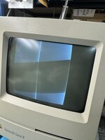
Hi all! First time poster. I obtained a Classic II while back and am not restoring it. Apparently I am a glutton for punishment because I haven’t given up yet. I cleaned and recapped and resoldered the Egret chip.

The problem is that computer boots with the bing sound (good!) but no video and no high voltage (boo) — but first I want to ask about something odd I found testing the voltage.

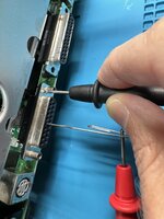
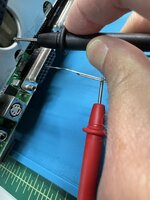
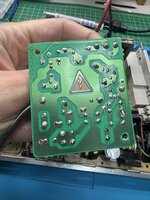
When I check for 5v and 12v through the floppy port, if I connect to ground on the floppy port connector or another shield on the logic board (eg the outsides of the DIN connectors), I get 0.335v and 1.262v respectively. However, if I put my probe on the computer case shielding, I get 5.074v and 12.19v.

Does that make sense? What is going on here? Photos of the measurement approach attached.

Thank you,
Bob
 

Attachments

  • IMG_7961.jpeg
    IMG_7961.jpeg
    859.1 KB · Views: 20
  • IMG_7963.jpeg
    IMG_7963.jpeg
    1 MB · Views: 15

bpetersen

Active member
For clarification:
  • All caps on analog and LB were replaced. Some were leaking.
  • I cleaned the logic board vis IPA scrub, then soak in hot water and soap, then scrub then soak in ipa and then toothbrush scrub
  • Verified there is no high voltage via audio spectrum analyzer, and also no static when touching the screen
  • The CRT doesn’t light up at all
  • Pressing Reset resets with a new bing. Pressing the NMI makes a cool set of sounds
  • I checked for cracked solder joints on the analog board and found none. I reflowed all the big solder joints (connectors etc) anyway, but in most cases didn’t remove and add new solder
  • I tested most of the resistors on the analog board - no issues.
  • Fuse and RAM tested good
  • Floppy and HDD are disconnected
  • No battery leakage. Replaced the battery.

So my questions are, does my voltage reading above make sense? Either way, given these specific symptoms, what would the next step be?

Bob
 

bibilit

Well-known member
If you are getting the chime, your Logic board is ok and probably both voltages also (so the reading above is ok... your 12 Volt rail is a bit high but still ok)

So probably your issue is somewhere in the Analog Board.

Please check that the loom from the AB board to the Neck board is ok and that you have no broken wire or cracked joint.
 

bpetersen

Active member
Thank you for the help! I will check the wires going to the neck board as well as the neck board itself. Are there documented voltages on the neck board or those wires I can check?
 

bpetersen

Active member
@bibilit, I checked the neckbeard connections and they looked fine. I reflowed all the large connections on the neck board anyway. Then I checked connectivity from the AB to the neck board for all wires. No problems. Retested and no change.

While running, checked the voltages on the seven wires at the neck board. They measured:

Neck board wire voltages:
Red: 0.075v
Orange: 5.74v
Yellow: 0.007v (i.e. ground -- expected? )
Black: (ground)
Brown: 12.18v
Blue: 0.168v
Green: 2.18v

Are these correct?

Thanks,
Bob
 

bpetersen

Active member
Ah, yes! I do mean that section. I am measuring where the wires come from the AB to the neck board. Sorry, I should have used component numbers. Here they are:

Neck board wire voltages:
HC6 (Red): 0.075v
HC2 (Orange): 5.74v
HC3 (Yellow): 0.007v (PROBLEM??)
HC1, HC8 (Black): (ground)
HC5 (Brown): 12.18v
HC7 (Blue): 0.168v
HC4 (Green): 2.18v

My AB revision is 630-0525-B, which doesn't seem to be listed in the Bomarc schematics.
 

Attachments

  • IMG_8006.jpeg
    IMG_8006.jpeg
    1.2 MB · Views: 12
  • IMG_8008.jpeg
    IMG_8008.jpeg
    1.7 MB · Views: 12

bibilit

Well-known member
If i am reading correctly, and schematics are ok too, this is what you should get :


HC6 (Red): 0.075v > should be 316 v
HC2 (Orange): 5.74v > should be 30.7 v
HC3 (Yellow): 0.007v > OK Ground
HC1, HC8 (Black): (ground) > OK Ground
HC5 (Brown): 12.18v > OK 12.00 V
HC7 (Blue): 0.168v > should be 211 v
HC4 (Green): 2.18v > should be - 40 v

Wondering if some readings are DC and others AC... but can be wrong here, never checked this part myself.
 

bpetersen

Active member
Thank you, I think I am heading on the right track now. I am going to dig deep into this with an EE friend and try to figure it out. I found and verified all the voltages on the power supply side of the AB with them (+306v measured +323v, but the others +38v, +12v, +5v, -12v are right on), so something must be going wrong on the CRT side of the circuit.

It is very odd that +38v measured correctly but I am not getting the +30.7v at HC2, which should be just on the other side of DP13 from the +38v. I didn't measure that point on the board yet, although according to the schematic it should be the same as HC2. In fact, the 30.7v also seems to go into the Meritron part (high voltage flyback transformer?) so maybe that is the problem. I will probe some more tomorrow.

Looking more closely, I think you are also right that some of the HCx voltages are signals and not pure voltages, at least for HC4 (brightness) and HC3 (video signal).
 

joshc

Well-known member
I am sure you know this but please be careful measuring off the yoke - high voltages on there indeed !

In terms of the tube not initialising, does the tube itself look intact, on the yoke end? any cracks or splits there = dead CRT
 

bibilit

Well-known member
You have got several resistors on the way, maybe some are leaky and voltage is lost in the process.
 

bpetersen

Active member
Update: my problem definitely is linked to not seeing the 30.7v DC supply voltage. Today I checked everything around and including the IP2 LM317T voltage regulator. All the caps are new and correct orientation, resistors all good, and DP13 good. I replaced IP2 as well. Still no 30.7v.

Next the plan is to look at the users of the 30.7v to see if any of them are bad and pulling it down. I’ll first remove HV2, then QL2, then if it is still not working, remove the CRT flyback transformer ZL1 itself to isolate the supply voltage. It seems one of those has to be the problem.

Either way, not having the 30.7 volts DC into the flyback transformer seems like it would definitely be the cause of no high voltages coming out of it, as I am seeing.
Hello, try to control the IP2 “LM317” and if it’s good maybe it’s C11 cap 220mf/50v gone
 

bpetersen

Active member
Progress! I found at least one problem. After removing QL2 (the IRF740 power mosfet), now I get 30.7 volts at the expected locations. I tested the transistor and it is definitely not switching, so I have a new one on order arriving tomorrow.

Who wants to guess what problems show up once this is fixed? :)
 

bpetersen

Active member
I solved it! Replacing the QL2 (IRF740 power MOSFET) with a new one from Amazon (Anchor Electronics does not stock this, sad Mac...), and putting everything together, I get a screen! Now I need to:

1. Get a keyboard! I wasn't sure I would get far enough to need one. Anyone in the CA Bay Area have one for sale?

2. Fix this awful screen geometry. Messing with the knobs on the back just made it worse (photo with the vertical lines). Anyone know next steps for this? Seems like more than simple knob twisting.
 

Attachments

  • IMG_8052.jpeg
    4.2 MB · Views: 5
  • IMG_8056.jpeg
    IMG_8056.jpeg
    1.5 MB · Views: 9
Top