JC8080
Well-known member
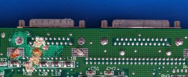
I just wrapped up my SE/30 reloaded build. When it came time to transplant the external floppy connector from my donor board to my reloaded board, I was a bit stumped. On some versions of the SE/30 the ground posts of the external connectors solder to the board "normally" - the post comes through from the top and is soldered on the bottom. On my version of the board the connectors are essentially riveted on, and then the holes in the rivets are filled with solder.

What I decided to do was first remove as much solder from the holes of the rivets as I could. Since these go directly into the ground plane, I needed to use a lot of hot air to get the solder to melt, then quickly used my iron and some wick to remove as much solder as I could. I really just wanted some sort of divot to use to center my drill bit. Then I took a drill bit that was a bit bigger than the head of the rivet and carefully drilled the head off until it was just below the bottom surface of the board
.
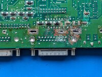
This took very little pressure on the drill. Once this was done, I moved on to the actual connector pins. I used an iron and wick to remove as much solder as possible, and then switched over to hot air since I was unable to remove all the solder from some of the pins. A few of my pins had very bad corrosion so I ended up needing to get quite aggressive with the hot air and a screwdriver to pop the connector off the donor board, losing half a pin in the battle.
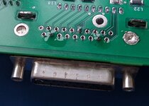
Once I had the connector out, I used a file to clean up the top edges of the posts I drilled, to make sure they would fit through the holes in my reloaded board. After that was done, the posts fit nicely into the reloaded board. I then turned my iron heat way up and used a bunch of solder to fill the holes, I wanted to make sure the connector had as much structural support as possible. In the photo you can see one post that I have not yet added solder to, and the other I started to fill with solder but did not yet finish.

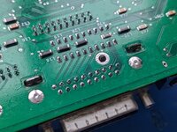
Once I filled the holes fully with solder I ended up with a very clean appearance. Fortunately, the half pin that remained on the upper-left pin was enough to take solder and make a good connection, so I didn't have to get fancy and bodge things.

Hopefully someone who runs into the same problem will find this post useful.

What I decided to do was first remove as much solder from the holes of the rivets as I could. Since these go directly into the ground plane, I needed to use a lot of hot air to get the solder to melt, then quickly used my iron and some wick to remove as much solder as I could. I really just wanted some sort of divot to use to center my drill bit. Then I took a drill bit that was a bit bigger than the head of the rivet and carefully drilled the head off until it was just below the bottom surface of the board
.

This took very little pressure on the drill. Once this was done, I moved on to the actual connector pins. I used an iron and wick to remove as much solder as possible, and then switched over to hot air since I was unable to remove all the solder from some of the pins. A few of my pins had very bad corrosion so I ended up needing to get quite aggressive with the hot air and a screwdriver to pop the connector off the donor board, losing half a pin in the battle.
Once I had the connector out, I used a file to clean up the top edges of the posts I drilled, to make sure they would fit through the holes in my reloaded board. After that was done, the posts fit nicely into the reloaded board. I then turned my iron heat way up and used a bunch of solder to fill the holes, I wanted to make sure the connector had as much structural support as possible. In the photo you can see one post that I have not yet added solder to, and the other I started to fill with solder but did not yet finish.

Once I filled the holes fully with solder I ended up with a very clean appearance. Fortunately, the half pin that remained on the upper-left pin was enough to take solder and make a good connection, so I didn't have to get fancy and bodge things.

Hopefully someone who runs into the same problem will find this post useful.
