You are using an out of date browser. It may not display this or other websites correctly.
You should upgrade or use an alternative browser.
You should upgrade or use an alternative browser.
SE/30 - Design for Drop in Replacement Power Supply
- Thread starter (o';'o)
- Start date
From what I can see the connector wires are soldered directly to the PCB, meaning over time there is a possibility of the wire breaking at the solder point.
A better solution if you are selling them would be to use crimp PCB terminal pins and solder those instead.
A better solution if you are selling them would be to use crimp PCB terminal pins and solder those instead.
Compgeke
Well-known member
@mg.man - I probably won't be selling PCBs only. I do sympathize about the cost for international shipping, VAT, duties, etc., but I want to avoid selling anything that would resemble a 'kit'. There is a lot more 'customer support' in this situation, even if you state that no direct support is available. I prefer to sell a working and tested unit as that eliminates variables and excess communications.
Heads up this *may* not be the best idea from a legal standpoint. A complete PSU will very very likely need to go through a bunch of safety/compliance checks to sell in many countries. UL/TUV is not cheap. You'd be opening yourself up to a lot of liability if one were to somehow fail and cause "damage to people or properties" as organizations such as NFPA put it.
This is actually such a headache there're products you can get from big companies like Ryobi or Unifi that integrate an off-the-shelf power brick into the machine and plug into the boards. This gets around needing to have the stuff certified.
zigzagjoe
Well-known member
I'd be curious to see the details of the communications with meanwell regarding the common ground reference across the modules... I could envision some uses for those myself.
Also, just to verify, are you measuring voltages at the PSU, or at the logic board?
The reason I ask is it's typical to find with retrofits that the PSU is outputting a steady 5v, but due to voltage drop before hitting the LB, the LB only sees 4.8v (or worse) depending on cards installed. The stock PSUs allow you to adjust the output to mitigate, but usually modern units don't allow this. Replacing the 22ga 5v wires in the harness helps some, but it's more in the manner of reducing losses rather than bringing voltage back to a solid 5v.
(o';'o)
Active member
The original PSUs did use the crimp terminal pins to solder to the PCB. I would argue that they are not necessary. Wire breakage has to do with repetitive movement over extended periods of time. The wire becomes work hardened with every movement, looses flexibility, becomes fragile, and eventually breaks. Direct soldering can exacerbate this condition.From what I can see the connector wires are soldered directly to the PCB, meaning over time there is a possibility of the wire breaking at the solder point.
A better solution if you are selling them would be to use crimp PCB terminal pins and solder those instead.
However, in these power supplies and computers, vibration is nil. The PSU is installed once and effectively remains fixed and static for the duration of it's life. Soldering offers the best ohmic connection, reducing resistive voltage drops, thus improving load regulation. If I were designing for electronics to be taken on the go, installed in a car, bike, etc. I would certainly consider an a different attachment method.
-Chris
(o';'o)
Active member
I'm a big fan of the IRM series, and Mean Well in general. I've never encountered a bad module and they always perform as you expect. For your projects, I would suggest that you reach out to them directly. The correct contact email can be found on their website depending on the country you reside. My experience has been that the provide a response in 3-5 days.I'd be curious to see the details of the communications with meanwell regarding the common ground reference across the modules... I could envision some uses for those myself.
Also, just to verify, are you measuring voltages at the PSU, or at the logic board?
The reason I ask is it's typical to find with retrofits that the PSU is outputting a steady 5v, but due to voltage drop before hitting the LB, the LB only sees 4.8v (or worse) depending on cards installed. The stock PSUs allow you to adjust the output to mitigate, but usually modern units don't allow this. Replacing the 22ga 5v wires in the harness helps some, but it's more in the manner of reducing losses rather than bringing voltage back to a solid 5v.
@JdM74 has been my main contact for in-computer load testing. His communications to me were that the measurements were taken at the floppy connector (measurements posted earlier in this thread).
(o';'o)
Active member
Heads up this *may* not be the best idea from a legal standpoint. A complete PSU will very very likely need to go through a bunch of safety/compliance checks to sell in many countries. UL/TUV is not cheap. You'd be opening yourself up to a lot of liability if one were to somehow fail and cause "damage to people or properties" as organizations such as NFPA put it.
This is actually such a headache there're products you can get from big companies like Ryobi or Unifi that integrate an off-the-shelf power brick into the machine and plug into the boards. This gets around needing to have the stuff certified.
There are risks and liabilities to be aware of when selling any product, and there are a number of ways to protect yourself and the customer.
First, I operate and make sales under my business, Baby Face Electronics LLC. This offers some base level of liability protection as a manufacturer and seller as it provides some separation of my business and personal finances.
Second, for offline power supply designs I utilize complete modules that take care of the critical task of rectification and isolation. I particularly like Mean Well products. They all come with the complete suite of certifications that apply world wide - UL, CE, TUV, etc. This offers another level of protection, documentation, and quality control.
Third, product insurance is one of the best ways to protect a small company from all sorts of liabilities and lawsuits. It is not required, but can prove extremely beneficial. A company can be sued by an individual, even when the individual intentionally missuses a product or causes harm by negligence. I am currently working to get a plan in place for my LLC.
Fourth, just plain good design.
Getting a product tested and listed by an NRTL is very expensive and time consuming. It is really only something that is pursued by medium to large companies. I work as an equipment engineer, and I regularly install equipment that is not NRTL certified (there are lots of large companies don't bother due to the cost, time, and other implications). However, my workplace/local authorities require NRTL certification on all equipment. I then work with a local agency to have everything NRTL Field Certified to the applicable standards.
So, if for some reason you wanted to install an SE/30 at your workplace and your workplace, state, or local jurisdiction required NRTL certification, you must have your SE/30 field inspected by a representative of a Nationally Recognized Testing Laboratory. Thus, the burden is not on me as a manufacturer to provide NRTL certification, but rather on the customer to meet the requirements of the installation location.
I'm definitely not an expert in this field, especially as a manufacturer, but there are many small companies that produce electronics and equipment that do not have their products NRTL listed/certified. It would be a literal company killer if that were the case. I would be super curious to get other folks experience, knowledge, and opinions on that matter, as it is an important subject.
-Chris
(o';'o)
Active member
Hey All,
I posted the PSU installation instruction video to YouTube. Go easy on me.... this is my first time making a how-to video, let alone any form of video content. I certainly learned a lot but am happy to be done and release what I recorded. I suppose finished is better than perfect.
I posted the PSU installation instruction video to YouTube. Go easy on me.... this is my first time making a how-to video, let alone any form of video content. I certainly learned a lot but am happy to be done and release what I recorded. I suppose finished is better than perfect.
danny.gonzalez.0861@gmai
Well-known member
You did a great job with the video and the replacement! keep up the great work!Hey All,
I posted the PSU installation instruction video to YouTube. Go easy on me.... this is my first time making a how-to video, let alone any form of video content. I certainly learned a lot but am happy to be done and release what I recorded. I suppose finished is better than perfect.
zigzagjoe
Well-known member
@(o';'o) kindly provided one of these units to me for review.
TL: DR; it tests same or better than a seasonic and I would recommend it, especially if you are adverse to doing a recap.
It was easy to install as long as you're handy with a soldering iron. Level of effort is less than a seasonic retrofit. Design of board and quality of soldering/harness is good. Harness coming off the PSU is slightly short, but not problematically so.
I do not have any concerns with the design of the unit. After performing further research on my own, I've found that connecting independent AC-DC with common references seems to be a blessed scenario for these modules and similar from other manufacturers.
Takeaways:
Voltages: All voltages measured with Fluke 233 at LB PDS slot and double checked with scope.
Efficiency: Kill-a-watt for AC power draw, combined with Fluke ammeter readings on the DC side
Test scenario:
I tested both a stock harness as well as a stock harness with the 5V wires replaced with 16ga wires for testing.
All units had some degree of "slow" voltage rise/dip on the after dark scenario, separate from noise. I didn't outright measure this, but on average it seemed to be around 50mv and was largely consistent between PSUs. This would be switching noise from CPU activity changing, not something I'm concerned about, just a fact of life. This serves as a good reminder that quality of your measurement device can influence voltage measurements: You may get artificially high readings since cheaper devices may end up measuring more the maximum voltage rather than average voltage.

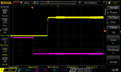
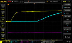
Power sequencing looks good. There is a slight delay from flicking the power switch to power delivery - not a problem, just different. Rise times look good and ordering is fine & seems consistent. Yellow=5V, Blue=12V, purple= -12V.
Ignore noise: this measurement was performed with poor ground.


Additional tests performed:


TL: DR; it tests same or better than a seasonic and I would recommend it, especially if you are adverse to doing a recap.
It was easy to install as long as you're handy with a soldering iron. Level of effort is less than a seasonic retrofit. Design of board and quality of soldering/harness is good. Harness coming off the PSU is slightly short, but not problematically so.
I do not have any concerns with the design of the unit. After performing further research on my own, I've found that connecting independent AC-DC with common references seems to be a blessed scenario for these modules and similar from other manufacturers.
Takeaways:
- Retrofit PSU beats the Seasonic in static efficiency measurements as well as noise
- Modern PSUs reduce heat in the case by ~10 watts in a heavily loaded scenario.
- 15% reduction in heat inside the case in a heavily loaded machine is nothing to scoff at!
- Upgraded 5V wires on AB->LB harness are essential with multiple expansion cards
- Sony PSUs put out good quality 5v, but are (forgivably) inefficient due to age
- Display wiggle was not an issue with any of the tested units on HDD access
- thinking I'm experiencing magnetic noise from the HDD actuator when HDD is installed in chassis.
- For stock machines, any PSU be it recapped or retrofit is suitable.
- I took some measurements for this, but it's not terribly useful info.
Voltages: All voltages measured with Fluke 233 at LB PDS slot and double checked with scope.
Efficiency: Kill-a-watt for AC power draw, combined with Fluke ammeter readings on the DC side
Test scenario:
- SE/30 with recapped AB, external Zuluscsi, 32MB RAM in 8 SIMMs, stock ROM and a 500MB apple HDD (no floppy).
- Cards: Socketed Carrera@45mhz, Asante MacCon, 30Video GS, Interware GrandVimage
- MacCon had ethernet link, 30Video GS and GrandVimage were driving external monitors.
- System 7.5.5
- 1: idle at finder desktop
- essentially busy-waiting doing nothing. Consistent noise.
- 2: after dark running the shapes screensaver
- introduces CPU load, bus activity resulting in noise on 5V.
- Efficiency measurements taken from a static load test under following conditions: 6A 5V, 2.7A 12V, 0.6A -12V
I tested both a stock harness as well as a stock harness with the 5V wires replaced with 16ga wires for testing.
All units had some degree of "slow" voltage rise/dip on the after dark scenario, separate from noise. I didn't outright measure this, but on average it seemed to be around 50mv and was largely consistent between PSUs. This would be switching noise from CPU activity changing, not something I'm concerned about, just a fact of life. This serves as a good reminder that quality of your measurement device can influence voltage measurements: You may get artificially high readings since cheaper devices may end up measuring more the maximum voltage rather than average voltage.

Power sequencing looks good. There is a slight delay from flicking the power switch to power delivery - not a problem, just different. Rise times look good and ordering is fine & seems consistent. Yellow=5V, Blue=12V, purple= -12V.
Ignore noise: this measurement was performed with poor ground.


Additional tests performed:
- Maximum load test passed with convection cooling only
- 1hr @ 9.5A 5V, 4.5A 12V, 1.25A -12V
- No issues, 5V module was hot though within spec. 75 deg C surface temp at the end.
- Overnight load test passed without issue
- 16hr @ 6A 5V, 2.7A 12V, 0.6A -12V


(o';'o)
Active member
Thank you @zigzagjoe for your thorough testing! This is much more than I was expecting and am very grateful for your time and effort. You're a legend!
zigzagjoe
Well-known member
Happy to help. Also - Oops - I spotted a typo in the chart above - Retrofit Psu with 16ga wire had 4.88v idling at finder desktop, not 4.8v.
Expanding on sequencing: I don't think there's any issue with -12v (and thus -5v) coming up early; -12v is only used for audio amp which doesn't have sequencing requirements, and -5v is only used for serial drivers which the datasheet says sequencing is not an issue.
Expanding on sequencing: I don't think there's any issue with -12v (and thus -5v) coming up early; -12v is only used for audio amp which doesn't have sequencing requirements, and -5v is only used for serial drivers which the datasheet says sequencing is not an issue.
Last edited:
tt
Well-known member
This is cool to see! I may be in the market for a new PSU, but need to do some troubleshooting to be sure. I have a spare Seasonic, but I am not sure if I should do another conversion since I think I saw some complaints about it a while back. I am wondering if you are thinking of providing a DIY kit for these. I like to assemble the wire harness with the same wire colors that the original machines used. I might also want put a connector on the board side to make the harness modular (like I did with the Seasonic conversion.Thank you @zigzagjoe for your thorough testing! This is much more than I was expecting and am very grateful for your time and effort. You're a legend!
wildstar1063
Active member
I ordered this power supply from the eBay listing, and got it Saturday afternoon.
I took it out of the box and removed the analog board from my SE/30,
took the Sony power supply off and gutted it and installed this in it's old housing. The only issue
I had was that the non contact alignment hole for the connector on the Sony power supply side of
the new board seems to be drilled off a bit from the pin on the included connector. I had
my Dremel handy and just made that middle no contact alignment hole just a tiny bit bigger
an everything went together well, I have not put the Mac back together yet as I am waiting for
other parts to arrive, but I did plug the power supply in and the fan spun up and the unloaded
voltages looked good on my meter.
Chuck E.
(o';'o)
Active member
Hey Chuck!I ordered this power supply from the eBay listing, and got it Saturday afternoon.
I took it out of the box and removed the analog board from my SE/30,
took the Sony power supply off and gutted it and installed this in it's old housing. The only issue
I had was that the non contact alignment hole for the connector on the Sony power supply side of
the new board seems to be drilled off a bit from the pin on the included connector. I had
my Dremel handy and just made that middle no contact alignment hole just a tiny bit bigger
an everything went together well, I have not put the Mac back together yet as I am waiting for
other parts to arrive, but I did plug the power supply in and the fan spun up and the unloaded
voltages looked good on my meter.
Chuck E.
Thanks for your purchase. Sorry you had some alignment issues. I’d be curious to follow up with you a bit more to make any adjustments to my component footprints on the next run of PCBs.
Just to clarify - The Sony connector footprint is designed for the original header part only. You can remove the original Sony header and install it on the new PCB. The included Molex header is not to be installed in the Sony location (or vise versa).
Drop a picture in this chat if you can or send me a direct message.
Thanks!
Chris
wildstar1063
Active member
I guess that was my mistake, I used the included connector on the Sony footprint on the board,
instead of un-soldering the original Sony connector. The soldered pins on each end of the connector
fit perfectly, but the pin in the middle. Is off just slightly and I had to find a drill bit to make it work.
But since there's no solder connection there, it doesn't really matter. The amount that the hole is off
from the connector is small enough that I could have probably just used a small round jewelers file
and fixed it, but I had the Dremel setting there, and I just dug through the bits till I found one that
was slightly larger and used it to make the hole bigger. Everything else went perfectly. I just didn't
realize I was supposed to use the original pin header from the old Sony power supply. But I wanted
to keep it Intact anyway, because I was thinking about recapping it and keep it as a back up.
Oh well, live and learn
Chuck E.
Similar threads
- Replies
- 0
- Views
- 397
