• Updated 2023-07-12: Hello, Guest! Welcome back, and be sure to check out this follow-up post about our outage a week or so ago.

SE/30 - Design for Drop in Replacement Power Supply

tvj

Member
There is also this old upgraded one

I found while searching what power supply is best in the se/30
 

(o';'o)

Active member
Hi @cooltr6 - I should have been a bit more clear in my previous post. The Singapore and Astec versions are different, both in PCBs and metal enclosure. I had originally believed that there were two Astec versions, but in fact there is only one. So, as it stands, there appear to only be three versions:

699-5047
(ASTEC AA13800)
(SONY CR-44)

631-5105-A
(MADE IN
SINGAPORE)

Thank you both, @cooltr6 and @RepairManiac, for verifying the umbrella OEM part number (661-0370).

@codevonlux - I took another look at the 'Singapore' version and could not find any Hitachi identifying marking or lettering. However, I do find it interesting that this is the only power supply version that actually bears the Apple name. In this case, both on the metal enclosure and on the PCB. See attached pictures.

@tvj - That is a very interesting post you've linked in - Many thanks! I have seen other Power Plus Systems SMPS in 80's equipment, though they have a tendency to produce a lot of heat and fail in similar fashion to other antiquated SMPS designs. It is especially interesting to see 3rd party manufacturers with a replacement PSU of that era. It would indicate that there were enough SE/30 owners who found the original PSU inadequate. It's also informative that the PPS-101 had a 5A output capability on the +12V line. I would be curious to find out if they had a similar diode isolation scheme for the Disk and Sweep circuits.
 

Attachments

  • IMG_6726.jpg
    IMG_6726.jpg
    1.6 MB · Views: 90
  • IMG_6727.jpg
    IMG_6727.jpg
    2 MB · Views: 52
  • IMG_6728.jpg
    IMG_6728.jpg
    1.7 MB · Views: 50

mari3311

Active member
Hello (O’;’O).

*
I have also read https://68kmla.org/bb/index.php?threads/modern-psu-for-the-se-30.30945/ many times.
I would like to express my thoughts on your question (2).

Rail 1: Sweep cirduits
  11.5-12.5V 1.25A

A voltage regulator SI-3122V (12V, 2.0A) is used for both Sony (CR-44) and Astec power supply (Bomarc schematics) because a stable voltage is required here to prevent the screen display from shaking.

Rail 2: Disk Drive
  12V 2.1A

This is the same as the 5V 6A and -12V 0.5A power supplies, and is composed of a general voltage circuit.

In other words, only the “Sweep cirduits” requires a stabilized power supply, and the others do not require strict performance.
(However, the 5V power supply is 4.85V or more, and the 12V for disks is a maximum of 4A for 15 seconds after power is turned on.)

I believe that the reason why the SE/30's 12V power supply has two rails is because around 1989, there were only a very small number of voltage regulators that could regulate a current of 1.25 + 2.1 = 3.35A or more at 12V output.

***
I don't have any documentation on the voltage regulator products available around the world at the time, but I read the following from Digikey's online inventory list for Voltage Regulators - Linear (66,800 types)as of 2024:

Of the 66,800 types, 668 output 12V.
Of these, 47 have a current of 2.0A or more. (30 types are discontinued, and 17 are current products.)
Of the 47 types, there are only two discontinued products and one current product that exceed 3.0A.

Even now, when semiconductors are becoming increasingly high-powered, a voltage regulator that can handle 3.0A or more at 12V is a rare entity.

Even if there was a voltage regulator that could handle such a large current back in the day for the SE/30, it would have been over-specified and a waste of money.
 

mari3311

Active member
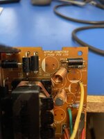
Next, in terms of the circuit, the reason why the SE/30's 12V power supply has a Di (SONY ERA81-004, Astec FE2A) between the two rails is that it clips (suppresses) the unregulated 12V for the disk drive to around 13.0V to match the regulated 12V for the sweep, so that the voltage doesn't become too high.

  Max. Disk 12V = Sweep 12.0V+Forward Drop Voltage (1.1 to 0.98V)

     ERA81-004   40V, 1A VF=0.55V (x 2pcs)
     FE2A      50V, 2A VF=0.98V

There is no need to insulate the 12V on the disk side from the 12V on the sweep side.

This is because the windings in the transformer (T151 for Sony, 06890 for Astec) are separated for each 12V to generate independent 12V DC, and if you connect it with a diode, the 12V on the disk side will be linked to the sweep voltage as shown in the following formula, and it will no longer be "independent", and you will lose the reason why it was generated independently from the transformer.

If spike output from the Sweep side is a problem, I think it would be common for electrical engineers to incorporate a diode for this purpose on the analog board as a output safety circuit, so I think it is reasonable to assume that the reason the diode is connected to the output of the voltage regulator on the power supply unit side is to utilize the "(stabilized) 12V output of the voltage regulator" (for the purpose of clipping).

*
From the above, my conclusion is that the reason there are two rails in the SE/30 12V power supply circuit is that the voltage regulator is only needed in a limited number of places, so they used only the voltage regulator with the appropriate capacity and saved on the rest, and the diode was inserted to suppress the upper limit of the 12V required for the disk by saving on the contrary.

What I did is the same as what superjer2000 and his colleagues achieved with their ATX power supply, which is that it's no problem to have just one 12V rail.

*
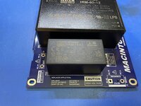
Over 30 years have passed since the SE/30, and voltage regulators have become much more stable, faster, and less susceptible to noise. Capacitors and noise filters have also become more powerful. Considering this, there is no need to use the exact same configuration as the SE/30, and it is fine to use a DC-DC converter currently on the market that provides +12V, -12V, and +5V.

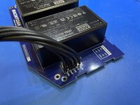
I used the MeanWell RT-85B three-output power supply unit as an alternative power supply unit for the SE/30, and was able to run the Xceed Grayscale display and the 68050 Accelerator SE/30 POWERCACHE, which is directly attached to the CPU socket, simultaneously on the SE/30 without any problems.

What I did is the same as what superjer2000 and his colleagues achieved with their ATX power supply, which is that it's no problem to have just one 12V rail.
 

codevonlux

Well-known member
Hi @mari3311,

I think all the power rails are "regulated". The 12V sweeping rail just has an additional LDO (Linear regulator) to further clean-up the noise from the switching noise that is common in this "switching" type of power regulator. Especially PWM controller in old days is oscillating in low frequency range (40KHz typical in MB3759 being used in Sony PSU) which is in the same range of the analog video circuity (HSYNC of ~20KHz) that will cause noticable artifact on the video. Modern switching power normally have a much higher switching frequency to avoid this.

Agree with you on the cost/maximum current trade-off for this, even a small voltage drop aross lenear regulator (13V to 12V over 1.2A) will still generate a lot of heat and I can see at least in the Hitachi PSU the LDO (LT1086-12) is stick to the enclosure with TIM to help with the heat dissipation. So the choice made here is to provide just enough current on this clean/sweeping rail and put other digital 12V in a separate noisy rail.
 

(o';'o)

Active member
Thank you @mari3311 and @codevonlux for your detailed responses. I was unaware that the PSUs had been reverse engineered, but that is a wonderful surprise. I have already finished my second version of the PSU replacement and have deleted the diode and capacitor isolation from the +12V rail. I had a couple other tweaks as well so it made sense to go ahead with a V2. I should have it back from the fab in a week or two.

@codevonlux - Thanks for pointing out the Hitachi logo. The PSU version I have has serious corrosion from leaky electrolytics which obscured the marking and text.

Once I have V2 back from the fab I'll be sure to post some pictures. Thanks everyone for your contributions - It's a massive help!

-Chris
 

(o';'o)

Active member
Hey Hey

I received the new PCBs and built a few up for a test fit - The mechanical details align to fit in all three styles of PSUs. Next, I'll be sending one off to test in a fully functional SE/30. Attached are a couple pictures of the final product.
 

Attachments

  • IMG_6889.jpg
    IMG_6889.jpg
    2.8 MB · Views: 80
  • IMG_6888.jpg
    IMG_6888.jpg
    3.2 MB · Views: 85
  • IMG_6887.jpg
    IMG_6887.jpg
    3 MB · Views: 90
  • IMG_6886.jpg
    IMG_6886.jpg
    3.1 MB · Views: 92

mari3311

Active member
Very nice work with the smart power supply unit.

I would like to hear your thoughts about the power supply unit you made, especially about the screen display using the Sweep power supply.

By the way, I made an alternative power supply using the RT-85B, also made by MeanWell, but there is something that is bothering me.
The Macintosh guide has the following to say about the Sweep power supply.

******
Guide to the Macintosh Family Hardware (P.260)
Table 6-17
DC output ripple and switching noise for the Macintosh SE and Macintosh SE/30 computers.

12V sweep

Line frequency ripple 30mV
Switching noise 50mv

******
IRM-60-12 (Data Sheet)

Output
Ripple & noise(max.) 120mVp-p

******

In the values on P.260, if a Ripple of 30mV and a Noise of 50mV overlap at the same time, the result is 30+50=80mV.
On the other hand, the IRM-60 and RT-85Bs 120mVp-p is an effective value of 120/1.414=84.9mV, so I do not think that this is significantly different from the limit value listed on P.260.
 

(o';'o)

Active member
@mari3311 - Excellent observations! Yes, the ripple + noise for the Mean Well IRM-60-12 states 120mVp-p in the datasheet, but I have found from experience that the ripple voltage is typically about 1/2 of what is stated as worst case. If you take a look at the report for the IRM-60-12 (https://www.meanwell.com/webapp/product/search.aspx?prod=IRM-60&pdf=SVJNLTYwLTEyLXJwdC5wZGY=&a=2), you'll see that they measured 68mV on their test sample under full load conditions. The ripple is also reduced as load current diminishes.

@Fred1212 - It's currently looking like pricing will be about $135.

@mg.man - I probably won't be selling PCBs only. I do sympathize about the cost for international shipping, VAT, duties, etc., but I want to avoid selling anything that would resemble a 'kit'. There is a lot more 'customer support' in this situation, even if you state that no direct support is available. I prefer to sell a working and tested unit as that eliminates variables and excess communications.
 

mg.man

Well-known member
I want to avoid selling anything that would resemble a 'kit'.
Totally understand... it's not so much looking to be cheap / and certainly not asking for a "kit" - which would imply all parts are included. A quick look here in the UK has the larger power modules working out at ~$20-25 each and the smaller at ~$10-15, so eliminating their weight and 'value' should reduce shipping and duties.

I don't know if there would be enough demand to consider a local "agent" - such as employed by the BS / ZS providers, but maybe that's another path worth considering?

Great work - looking forward to seeing the final version.
 

(o';'o)

Active member
Hey All,

The eBay listing is live! https://www.ebay.com/itm/266898469654

Price is set at $134.99 + shipping.

Take a look through the description and let me know if it all makes sense. I plan on making a cut and dry installation video in the near future, but since I've never produced content like that before, it's taking me longer than expected. Bit of a learning curve with that stuff...

Thanks to everyone for your help!

-Chris
 

eharmon

Well-known member
Any measurements of the voltage droop under load? The standard SE/30 supplies are known to commonly dip too low when loaded with a few cards.
 

(o';'o)

Active member
@eharmon - Jason of @JdM74 was kind enough to do some stress testing on this power supply. I am reposting his communications to me below. Note that the voltage measurements were taken at the floppy connector.

"First round of testing:
  • Stock SE and SE/30 [4MB RAM]
  • No boards installed
  • Spinning platter hard drive [Quantum 40MB]
  • Used an 800k disk to boot also
Both systems -- +12V was a solid 12.05V, +5 also solid 5.00V and -12V was at -11.98V

Second round of testing:
  • Not-so-Stock SE and SE/30
  • Accelerator board installed [for the SE, one by Novy systems - 25MHz 030] and a Carrera 040 [40MHz 040] in the SE/30.
  • In the SE - 4MB RAM
  • In the SE/30 - 8MB RAM
  • Spinning platter hard drive [same as above]
  • Used an 800k disk to boot also
Both systems -- +12V was a solid 12.03-12.05V, +5 hovered between 4.96 and 4.98V and -12V was at -11.93V"
 

joshc

Well-known member
This is an interesting project. What are the options for people not in the US?

A better test would be an accelerator + two PDS cards, thats about as loaded as these machines tend to get but quite a few people have that sort of configuration and would be looking for a power supply that can support that kind of load.
 

(o';'o)

Active member
@joshc - International shipping is available via the eBay listing.

I would be interested in getting additional in-circuit testing, however, I believe the specifications of the new power supply are a substantial improvement over the original. The 5V supply got a 66% increase in output current. The original and new PSU specs are listed below:

Original Apple PSU Specifications:

Input:
100-240VAC

Output:
+5V @ 6A
+12V Disk @ 2.1A
+12V Sweep @ 1.25A
-12V @ 0.5A


Replacement PSU Specifications:

Input:
100-240VAC

Output:
+5V @ 10A
+12V @ 5A
-12V @ 1.25A
 

zigzagjoe

Well-known member
Nice work. Those meanwell modules are cute. I'm interested that you were able to get away without the sweep rail, with a mechanical HDD present. I had to implement a diode/capacitor/inductor filter on my seasonic retrofit to cut down on HDD-induced screen wiggle. Those are also very good voltage figures if you are still running the stock harness to logic board (which will account for 0.1v+ voltage drop).

A thought though - given each module is an independent AC-DC, are they intended to operate with a common ground? That'd be somewhat unusual, and I don't see mention of it in the datasheet. I don't know enough to gauge the risks, but it may be worth looking into.

I'd suggest you may want to remove most of the technical detail from the listing - just a short blurb of specs - and move that elsewhere. Definitely keep a section on the requirements though (ie. not just drop in and go, you need to solder).
 
Last edited:

(o';'o)

Active member
@zigzagjoe - The 12V supply is robust, oversized and appears to be capable of maintaining proper load regulation as to not affect the display. I believe there is an additional benefit to having a new wiring harness installed to overcome the oxidation and parasitic resistance of the original Molex crimp connections. This will help any resistive voltage drops from the original.

I have used these power supply modules on a number of other power supply replacements. The outputs can be ground referenced and grouped as necessary (of course, no series or parallel secondary connections allowed). I have had email communications with Mean Well and I should note that each module is fused on the primary side.

I will probably edit the eBay listing to be more streamlined in the future once I’ve created the installation video. But as it stands, I thought it best to share as much information as possible until I have other means to disseminate.

@JdM74 was kind enough to put together an excellent pdf. I’ll ask him to post here for full visibility.

-Chris
 
Top