SE/30 Custom ROM Install Technique

jmacz

Well-known member
Hoping to hear from other members on their techniques to hold a third party ROM in place on an SE/30 (given the thinner PCB). This applies to the Rominator and others, in my case a SMC ROM.

I've seen the piece of paper and rubber band techniques. I'm currently using 3D printed clips I found online. But I think I'm still seeing issues from time to time.

I 've had some random crashes, mostly in random OS/ROM traps although a good number are during a Dequeue call. I was getting them consistently this morning (still random calls but consistently crashing) after I opened up the case to duplicate an SD card. Opening the case and running the machine without it is the only change. I remembered the ROM install being a little finicky and so on a whim, I decided to tilt the SE/30 at an angle to relieve pressure on the motherboard and all the crashes went away as long as I was holding the SE/30 that way.

Theoretically could be a bad trace, faulty solder joint, etc... but it wasn't doing this on the stock ROM so I am currently thinking it's due to the finicky contact of the ROM.

I'm currently using these clips:


zigzagjoe

Well-known member
Hoping to hear from other members on their techniques to hold a third party ROM in place on an SE/30 (given the thinner PCB). This applies to the Rominator and others, in my case a SMC ROM.

I've seen the piece of paper and rubber band techniques. I'm currently using 3D printed clips I found online. But I think I'm still seeing issues from time to time.

I 've had some random crashes, mostly in random OS/ROM traps although a good number are during a Dequeue call. I was getting them consistently this morning (still random calls but consistently crashing) after I opened up the case to duplicate an SD card. Opening the case and running the machine without it is the only change. I remembered the ROM install being a little finicky and so on a whim, I decided to tilt the SE/30 at an angle to relieve pressure on the motherboard and all the crashes went away as long as I was holding the SE/30 that way.

Theoretically could be a bad trace, faulty solder joint, etc... but it wasn't doing this on the stock ROM so I am currently thinking it's due to the finicky contact of the ROM.

I'm currently using these clips:


Definitely desolder and replace the ROM socket if it hasn't already been done. It's not worth fussing with the stock sockets; they get finicky even with the stock ROM over time much less any modern replacements. It's not worth the heartache, and you won't need any bodges to use a modern ROM.

These are suitable and good quality: https://www.peconnectors.com/sockets-pga-cpu-and-memory/hws1788/

You'll find it much easier than installing a CPU socket too.
 

jmacz

Well-known member
Definitely desolder and replace the ROM socket if it hasn't already been done. It's not worth fussing with the stock sockets; they get finicky even with the stock ROM over time much less any modern replacements. It's not worth the heartache, and you won't need any bodges to use a modern ROM.

These are suitable and good quality: https://www.peconnectors.com/sockets-pga-cpu-and-memory/hws1788/

So the new ones can handle the thickness (or lack of it) on the non-stock ROMs?

Looks like minimal order is $30 at phoenix. I'll look into it, thanks for the pointer!
 

zigzagjoe

Well-known member
So the new ones can handle the thickness (or lack of it) on the non-stock ROMs?

Looks like minimal order is $30 at phoenix. I'll look into it, thanks for the pointer!
Yep, they work fine with the 1.2mm PCBs!
 

jmacz

Well-known member
Trying to figure out how to use up another $27 on that site. Do they have the proper memory sockets there as well? I see angled ones and vertical ones, but the verticals seem to not be spaced properly for the SE/30 motherboard.
 

zigzagjoe

Well-known member
Trying to figure out how to use up another $27 on that site. Do they have the proper memory sockets there as well? I see angled ones and vertical ones, but the verticals seem to not be spaced properly for the SE/30 motherboard.
They only have single memory sockets, in both plastic (not tried them, don't know the quality) and metal tab (poor quality, avoid) versions. They do stock some 68030 PGA sockets and a variety of other IC sockets.

I usually can always use some PGA sockets, so that's an easy way to fill out orders. I'd recommend grabbing a ROM socket for any machine you have (which requires a ROM module, anyways) as it's truly not worth the trouble of having that as an additional point of failure.
 

jmacz

Well-known member
Feels like whenever you post that things are working, it jinxes you :) but here we go anyway.

The ROM socket @zigzagjoe recommended from PE worked great. Straightforward to get the old plastic one off and replace with the new one with metal clips. The ROM is in there securely now and I haven't seen an issue since installing them for a few days now. Appreciate the recommendation as always @zigzagjoe!
 

mari3311

Active member
I also solder directly onto the 1.2mm PCB.

*

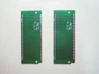
I will explain using a sample 1.2mm PCB.

First, apply a thick layer of solder to all pins.
(In my case, it was 1.5mm thick.The PCB on the left is normal 1.2mm.)
1735209190046.png

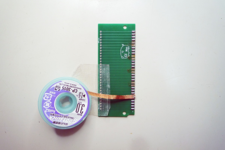
Next, use a solder wick to thin out 10 pins of solder from the 30-pin terminal at roughly equal intervals.
1735209251281.png

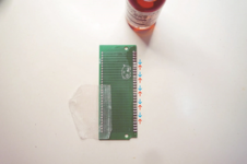
Clean with ethanol, apply flux, and use the tip of the iron to distribute the remaining 20 pins of solder evenly to the 30 pins in the direction of the arrow.
1735209307393.png

*

Result of the first run: thickness 1.5mm → 1.4mm

The second run was similar, with 10 strips thinned out and distributed across the entire 30 pins.
The result of the second run was a thickness of 1.4mm → 1.4mm, with almost no measurable change.

The third run was similar, with 10 strips thinned out and distributed across the entire 30 pins.
The result of the third run was a thickness of 1.4mm → 1.3mm, OK.


I placed additional solder on only one side of the PCB.

*
In this example,
(1.2mm) → 1.5mm → 1.4mm → 1.3mm


Using this method, you can thicken it to your desired thickness.
 

TrueNorthStrong

Well-known member
I’ve also just fattened up the board with solder. Not nearly as scientifically as this, just eyeballing it and a couple tests, trying to keep it as thin as possible while being consistent.

Probably a heck of a lot easier than swapping the socket, and if I ever want to set it back to stock I can.
 

zigzagjoe

Well-known member
That is a bad idea. You're simply kicking the problem down the road at best and will likely render the socket unable to work reliably even with a stock ROM.

If you've got the tools to thicken the solder, just grab a cheap desoldering iron or solder sucker and fix it the right way.
 
Top