philcollins
Member
Hey y'all,
Before I go on, I just wanted to say that what y'all are doing here is fantastic and I'm so glad to have found this community. Thank you for keeping these awesome machines alive and vibrant!
I was wondering if I might be able to ask for a bit of help with a Color Classic Mystic issue I'm running into. I performed the 640x480 modification today, following the standard Option 1 approach here:
 powercc.org
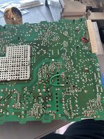
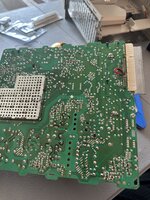
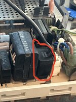
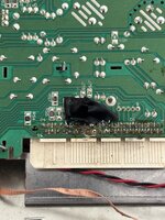
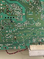
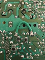
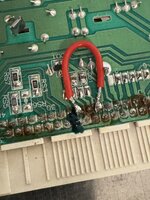
I checked my work, made sure that I hadn't cut any lines that weren't supposed to be cut and hadn't accidentally bridged any pins, then plugged the analog board back into the machine. I reattached all necessary cables (including the green ground wire), then took to undoing the 512x384 mod that had been made on the logic board:
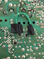
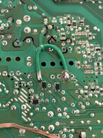
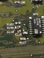
1. I removed the 4.7 kOhm resistor at R109
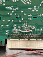
2. I made a solder bridge at R116
3. There was no resistor at R110 (and hadn't looked like one had been removed by the machine's previous owner), so I left it alone.
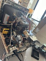
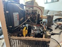
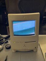
Upon my first post-mod powerup, the machine soft-powered on and chimed successfully, but the screen remained black. I realized that I'd made a rookie mistake: I'd neglected to plug the anode cap in the whole way, as I heard a few sparking noises. I removed power immediately, discharged the cap via the screwdriver-and-alligator clip method (for what it was worth) and ensured that all analog board connectors were properly connected.
However, despite these changes, the screen remains black and I can feel no static on the front of the screen, so I'm working to figure out why. There are a few positive signs:
1. The logic board reliably soft-powers on and chimes, and no Sad Mac songs play, so I don't think that I've fried the motherboard
2. When I switch the machine on, I hear the customary high-pitched charge sound
3. When the machine soft-powers on, I hear another customary high-pitched charge sound from the CRT and the big coil begins to make some sounds
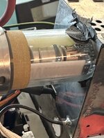
However, despite these signs, the tube at the neck of the screen does not glow orange, so I was wondering if y'all might have any ideas of where I might look for trouble here, as I fear that I'm stumped at the moment.
Thanks so much for the consideration!
--
Steve
Before I go on, I just wanted to say that what y'all are doing here is fantastic and I'm so glad to have found this community. Thank you for keeping these awesome machines alive and vibrant!
I was wondering if I might be able to ask for a bit of help with a Color Classic Mystic issue I'm running into. I performed the 640x480 modification today, following the standard Option 1 approach here:
640x480 | powercc.org
The Apple Color Classic is able to show more than 512x384 - by just a few changes it is able to show 640x480 - we show you how.
I checked my work, made sure that I hadn't cut any lines that weren't supposed to be cut and hadn't accidentally bridged any pins, then plugged the analog board back into the machine. I reattached all necessary cables (including the green ground wire), then took to undoing the 512x384 mod that had been made on the logic board:
1. I removed the 4.7 kOhm resistor at R109
2. I made a solder bridge at R116
3. There was no resistor at R110 (and hadn't looked like one had been removed by the machine's previous owner), so I left it alone.
Upon my first post-mod powerup, the machine soft-powered on and chimed successfully, but the screen remained black. I realized that I'd made a rookie mistake: I'd neglected to plug the anode cap in the whole way, as I heard a few sparking noises. I removed power immediately, discharged the cap via the screwdriver-and-alligator clip method (for what it was worth) and ensured that all analog board connectors were properly connected.
However, despite these changes, the screen remains black and I can feel no static on the front of the screen, so I'm working to figure out why. There are a few positive signs:
1. The logic board reliably soft-powers on and chimes, and no Sad Mac songs play, so I don't think that I've fried the motherboard
2. When I switch the machine on, I hear the customary high-pitched charge sound
3. When the machine soft-powers on, I hear another customary high-pitched charge sound from the CRT and the big coil begins to make some sounds
However, despite these signs, the tube at the neck of the screen does not glow orange, so I was wondering if y'all might have any ideas of where I might look for trouble here, as I fear that I'm stumped at the moment.
Thanks so much for the consideration!
--
Steve