• Updated 2023-07-12: Hello, Guest! Welcome back, and be sure to check out this follow-up post about our outage a week or so ago.

Quadra 630 ATX Adapter

CyberXZT

Member
Hi All!

I just noticed a link to this thread from Adrian's video.

I'm stoked about a possibility of a 630 series PSU solutions. Already had 3 of them buggers blow in quick succession.

It's also one of my very favourite 68K models too being mine is the DOS version with all the AV/networking gear. Oh and IDE, which saves a lot of headaches.


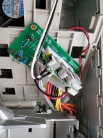
As it turns out, I was actually working on such a thing a few weeks ago. Attached is a picture of it.
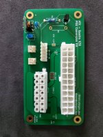
20200825_175049.jpg

20200825_174705.jpg

I've included an optional 3.3V power rail (for 3.3V boards) and optional -12V power (for power supplies that don't offer enough current or are extremely out of spec).

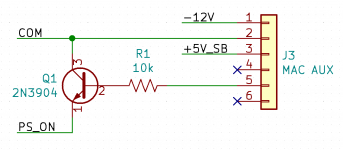
This is my first PCB and I am absolutely not an electrical engineer. I have not had the time to test it extensively although I have noticed some compatibility issues with some power supplies. I suspect it is something to do with the transistor/resistor combo. Maybe someone can spot a glaring oversight. Otherwise, I can describe the problem.

If there is enough interest, I am looking to make the project open source and maybe even ship out some kits.

 

CyberXZT

Member
I am currently using a picoPSU-160. It works nicely. It 'should' work with a picoPSU-120 however there is currently a compatibility problem that I am trying to work out.

There is also the issue of the power supply mounting. The Q630 chassis uses the power supply for structural reinforcement. Originally, I was going to make a 3d printed bracket that fits inside the original PSU chassis but I discovered that there are at least two different PSU cases with very different layouts.


JustG

Well-known member
As a new owner of a Performa 631 (I'm jealous of your DOS card) I'll be keeping an eye on this thread.


CyberXZT

Member
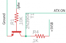
Maybe somebody here can give me a hand? The only issue I have had is with the soft power circuit. It looks like this:

Screenshot_20200826_190654.png

This is probably something stupid simple. So far, I have tested with the following:

2 assembled PCBs

Performa 636 Motherboard/PowerMac 6200 Motherboard

PicoPSU-120/PicoPSU-160

On one of my PCBs with the P636 motherboard and the PicoPSU-120, the machine does not start. The fan is nudged a moment and stops. All other tested configurations currently work. This has had me stumped for a few weeks and I kind of dropped it until Adrian's video today. Any ideas?

EDIT: To add further confusion, the specific issue only occurs when my ADB-USB Wombat is plugged in.

 
Last edited by a moderator:

Compgeke

Well-known member
Here's a sloppily trimmed and annotated version of the schematic from the mAcTX IIc. This is the setup I had to use to make soft power reliably work one everything. I've not tested this on a Q630 - but it does work on all the machines the board fits into. 

image.png


CyberXZT

Member
Thanks for the schematic! From my understanding, both designs should be functionally the same. Tomorrow, I'll pull out the oscilloscope and check and see if I can find anything obvious there. If not, I'll swap the transistor and see if that makes any difference.

I don't believe the resistor to +5V_SB is necessary as there should be an internal pull-up on the PSU. That was, at least, the case on the two PicoPSUs I tested. While I added a footprint for it on my PCB, I haven't populated it.


Compgeke

Well-known member
Alright so use this as constructive feedback and *not* criticism of the board - I want to help avoid the mistakes I did with the mAcTX board :)

So one of the first things I notice is you have the connector for the PicoPSU and the Mac harness on the same side of the board. I'd swap that Mac harness connector to the back side of the board, allowing for you to run the picopsu into the hole for the original PSU and keep the 12V lead for that going straight.

The next thing I'd do is try and keep all the small parts to one side of the board, away from the middle in between the two connectors. It'll look more pretty and professional, but also follow onto the next tip.

Switch to planes over traces. 5V and Ground shouldn't be traces, at all. Use planes right off the bat. The reason for this is it allows for a cleaner board layout and allows for higher current handling. You'll still have some rails like the +12V that need routed as a trace, but using a 75-100 mil trace will suffice, just run it around the outside edge of the board. These machines are very 5V heavy so you want to make all the space you can for that. 

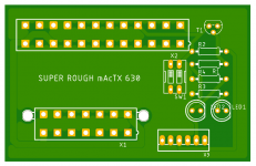
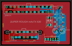
I've attached a couple images of a halfassed Q630 compatible board. It's basically a rough draft of what I'd do myself. It's basically a modification of the mAcTX IIc layout, but for a Quadra. 

image.png

image.png

image.png

image.png

 
Last edited by a moderator:

CyberXZT

Member
I can't believe it! My PicoPSU had a cracked solder joint. That's it. That's the problem. The PCB worked this whole time. Ahhhhhh!

Thanks for the feedback It is hugely appreciated. This is my first actual PCB :p

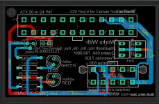
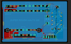
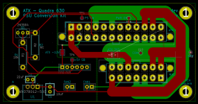
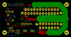
As for the layout. Ground is actually a plane on both sides of the PCB. Everything else is traces. I'm not to familiar with planes in KiCad but it is definitely something I want to improve on. Here is the layout:

Screenshot_20200826_225249.png

Screenshot_20200826_225320.png

If I did everything right, the current layout should allow for the following amperage limits (2oz copper):

3.3V - 6A
5V - 20A
12V - 12A
-12V - 2A

The components are somewhat haphazardly thrown around. It's ugly, but it works. Soldering is also pretty easy. I absolutely learned this the hard way from the original revision.

As for the connector placement, I intended on mounting the board vertical, rather than horizontal like the original PSU. On my P636 and PM6200 cases, all of the cables have a fair amount of room to reach the board.

Overall, I'm very happy. I can't believe I have been ignoring this for a month due to such a stupid problem. >.< I gotta thank you (and Adrian and his video) for making me look into this again. I intended on making something similar for my LC III and IIsi as well, but I suppose that might not be necessary anymore! Well, I'd probably still do it, at least for the fun/experience.

Over the next few days I will test this on more boards and decide where to go from there.


CyberXZT

Member
I went ahead and did further testing. So far, everything has worked well. The only issue has been the cracked solder joint on the PicoPSU mentioned above. I have tested the adapter with the following hardware:

Chassis:

63x

6200

Motherboard:

820-0548-B (63x)

820-0685-B (6200)

820-0751-A (5260)

820-0828-A (5400)

ATX PSU:

PicoPSU-120

PicoPSU-160-XT

Some additional notes:

  • The PicoPSU may not be powerful enough for all workloads. Additionally, the PicoPSU-120 was getting fairly warm during my testing. The PicoPSU spec-sheet recommends the addition of a fan when running under high load. The PCB provides a second fan header for this purpose. For my purposes, the PicoPSU-160 runs cool.
  • Regarding 3.3V: On both of my wiring harnesses, the wire used for 3.3V on later models is colored black for ground. This wire was left NC on the original power supplies tested. On my non-3.3V model motherboards, this pin is NC as well. Do any motherboards actually use this pin for ground? Either way, I left this as a solder jumper.
  • I have not done extensive testing with mechanical hard disks or mechanical floppy disks. I generally use solid-state wherever possible and do not have many working examples to test. I have also only tested a limited amount of peripherals, mainly Ethernet cards. I can't imagine any real incompatibilities in this front as long as the ATX PSU is powerful enough.

I expect to have more components in the next week or two. If anyone is crazy brave enough, I'd be willing to start sending out prototypes for only the cost of materials/shipping. I'll talk about this more at a further date.


CyberXZT

Member
Hi all,

Apologies for the long hiatus. Truthfully, I have been sitting on this for well over a year now and just don't have the motivation. I've decided to release the KiCad files on GitHub.

https://github.com/CyberXZT/atx-q630

I have tested the latest revision on a few different board/chassis/psu combinations and haven't run into problems. Nevertheless, I am not an electrical engineer. I take no responsibility for any damage these designs may cause. Use these designs with extreme caution. I am also not actively maintaining this. Questions/feedback may go unanswered.

Here are a couple quick notes:

  • R2 is unused.
  • U1, C1, and C2 are necessary if the PSU does not supply -12V. Do not populate these if you want to use the PSU's -12V rail. Instead, bridge the "ATX -12V" jumper.
  • 3.3V is not connected by default. The PSU on the original Quadra 630 and variants actually used this wire for ground. While the motherboards I tested did not actually connect this wire to anything, I have left it disconnected by default to be safe. If you need 3.3V, bridge the "ATX 3V3" jumper.
  • I can't a good connector for the 6-pin "MAC-AUX" connector. The BOM references the best fitting part although the smaller wall has to be cut in order for the connector to fit.
  • PCB was designed with 2oz copper in mind.

Licensed under Creative Commons Attribution-ShareAlike 4.0 International License.

 
This is excellent and will be the perfect replacement for my current ATX PSU bodge job.

For the record, if soft power isn't required, you can carefully pop all of the pins out of the Quadra PSU's connector and the appropriate pins out of the ATX connector (plus connect up some bodge wires to the aux connector) the machine seems to happily plug along. Even running the capture equipment on my 638AV works stably.

Looks like you took it a step farther and made soft power work (plus it's super clean).

Nice work. The disclaimer is appreciated but I think you can rest easy, this looks perfectly sound. I plan on ordering a few this evening.
 
Apologies for being clueless, but how do I go from downloading the files on GitHub to having some PCBs show up in the mail? I would like to get an old Q630 up and running. I don't mind soldering but I have no experience with CAD or ordering PCBs. Can anyone explain the process? I'd be happy to send you a board or two from the eventual order with my thanks.
 
Top