**********************************************************************
                      J   U   M   P   E   R   S
**********************************************************************
CONNER   CP3040  PRODUCT MANUAL 00501-016

 Jumper setting
 --------------

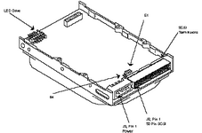
 J2  SCSI Connector Pin Assignments
 ----------------------------------
          +------------+--------+-------------+-------+
          | Signal     |Pin No. |   Signal    |Pin No.|
          +------------+--------+-------------+-------+
          | -DB(0)     |   2    |   -DB(1)    |   4   |
          +------------+--------+-------------+-------+
          | -DB(2)     |   6    |   -DB(3)    |   8   |
          +------------+--------+-------------+-------+
          | -DB(4)     |  10    |   -DB(5)    |  12   |
          +------------+--------+-------------+-------+
          | -DB(6)     |  14    |   -DB(7)    |  16   |
          +------------+--------+-------------+-------+
          | -DB(P)     |  18    |   GROUND    |  20   |
          +------------+--------+-------------+-------+
          | GROUND     |  22    |   GROUND    |  24   |
          +------------+--------+-------------+-------+
          | TRMPWR     |  26    |   GROUND    |  28   |
          +------------+--------+-------------+-------+
          | GROUND     |  30    |   -ATN      |  32   |
          +------------+--------+-------------+-------+
          | GROUND     |  34    |   -BSY      |  36   |
          +------------+--------+-------------+-------+
          | -ACK       |  38    |   -RST      |  40   |
          +------------+--------+-------------+-------+
          | -MSG       |  42    |   -SEL      |  44   |
          +------------+--------+-------------+-------+
          | -C/D       |  46    |   -REQ      |  48   |
          +------------+--------+-------------+-------+
          | -I/O       |  50    |             |       |
          +------------+--------+-------------+-------+
          The minus sign (-) indicates active low.
          All odd pins except pin 25 must be connected to ground.
          Pin 25 is left open.

 SCSI ID Jumpers
 ---------------
  +--------------+----------+--------+--------+-------+
  | Drive Select |   E1     |  E2    |  E3    |  E4/P |
  +--------------+----------+--------+--------+-------+
  |     0        |  OPEN    | OPEN   | OPEN   |   -   |
  |     1        |  CLOSED  | OPEN   | OPEN   |   -   |
  |     2        |  OPEN    | CLOSED | OPEN   |   -   |
  |     3        |  CLOSED  | CLOSED | OPEN   |   -   |
  |     4        |  OPEN    | OPEN   | CLOSED |   -   |
  |     5        |  CLOSED  | OPEN   | CLOSED |   -   |
  |     6        |  OPEN    | CLOSED | CLOSED |   -   |
  |     7        |  CLOSED  | CLOSED | CLOSED |   -   |
  +--------------+----------+--------+--------+-------+
  There are four jumpers available for configuration. Three of these
  jumpers, E1, E2, and E3, are used to select the drive's SCSI ID,
  installing E4 disables parity.


 E4  Parity Jumper
 -----------------

 E4     OPEN     Parity check enabled
        CLOSED   Parity check disabled


 J4  LED DRIVE CAPABILITY
 ------------------------
 1. 14-Pin Auxiliary Connector
    +--------------+
    |* * * *   * * |
    |  * * *   * * |
    +--------------+
    Pins 1 & 2 of the SERIAL IN/OUT connector may be used for an ex-
    ternal LED.

 2. 16-Pin Auxiliary Connector
    +----------------+
    |* * * * *   * * |
    |  * * * *   * * |
    +----------------+
    Pins 3 & 4 of the SERIAL IN/OUT connector may be used for an ex-
    ternal LED.

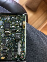
 3. Separate LED-Connector
    The newest drive-versions have a separate (white) LED-Connector


 J3  Power
 ---------
      +---------+
      | 1 2 3 4 |
      +-+-+-+-+-+
        | | | +----------- + 5V
        | | +------------- GND
        | +--------------- GND
        +----------------- + 12V


