-
Updated 2023-07-12: Hello, Guest! Welcome back, and be sure to check out this follow-up post about our outage a week or so ago.
You are using an out of date browser. It may not display this or other websites correctly.
You should upgrade or use an alternative browser.
You should upgrade or use an alternative browser.
Mac SE - Third of screen blurry/lines on screen
- Thread starter MacinPosh
- Start date
apm
Well-known member
It's probably the flyback then (which is an integral part of the horizontal circuit). If you have two machines, you could try swapping flybacks before finding a new one.
Do you have access to a scope? There are a few signals which could tell you what's going on.
Otherwise, another idea is to turn the brightness all the way up so you can see the scan lines. If the scan lines extend off the right side of the screen, then the problem might not be with the length of retrace but with its timing (starting too late), which would indicate a problem with the circuits driving Q2.
MacinPosh
Active member
Thanks Elfen and apm for the next suggestions. I'll try making those screen adjustments incrementally and see if it helps. The ferrite core does move and there is a noticeable change in the image width, but the lines just move with the picture as the width increases/decreases. I don't have a spare flyback I can try out, but I do have an analog scope to take measurements with.
apm
Well-known member
OK then, if your scope probe is rated to 200V or more (probably true if it is a 10:1 probe) then you can measure the voltage on C12. Careful though as a couple points on the analog board sit around 800V -- take the usual high-voltage precautions. You might even wire up the probe to C12 with the power off, and then switch the machine on. Attach the scope probe's ground clip to one of the ground points on the analog board (I use the metal cage around the flyback). Since the ground clip has to be attached by fingers, that should definitely be done with the machine off.
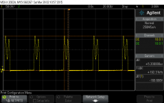
This measurement is from a working Plus but the circuit is essentially the same:

There should be a ringing pulse of 150-200V at a frequency of 22.25kHz. This is the yoke discharging energy into C12 every retrace cycle. The important part is that the whole pulse should be around 9us long (for comparison, HSYNC is low for 12us -- you can measure this on P4 pin 10 or U1 pin 1). If the pulse on C12 is much longer, then it indicates something wrong with the inductors or capacitors in the horizontal circuit. The flyback serves both functions, so a pulse that's too long is very likely a flyback failure. Other explanations are possible, but the flyback is a known failure point and can fail in all sorts of ways.
If on the other hand, the pulse is the correct length, then try the bright scan lines suggestion from my last post (which will tell you about the timing of HSYNC). If that's wrong, then the probably culprit is in the circuits driving the base of Q2.
The Classic has a horizontal centre control but the SE analog board doesn't. Personally I wouldn't mess with the CRT rings. They can move the picture around a little bit but they can't cause this kind of foldover.
This measurement is from a working Plus but the circuit is essentially the same:

There should be a ringing pulse of 150-200V at a frequency of 22.25kHz. This is the yoke discharging energy into C12 every retrace cycle. The important part is that the whole pulse should be around 9us long (for comparison, HSYNC is low for 12us -- you can measure this on P4 pin 10 or U1 pin 1). If the pulse on C12 is much longer, then it indicates something wrong with the inductors or capacitors in the horizontal circuit. The flyback serves both functions, so a pulse that's too long is very likely a flyback failure. Other explanations are possible, but the flyback is a known failure point and can fail in all sorts of ways.
If on the other hand, the pulse is the correct length, then try the bright scan lines suggestion from my last post (which will tell you about the timing of HSYNC). If that's wrong, then the probably culprit is in the circuits driving the base of Q2.
The Classic has a horizontal centre control but the SE analog board doesn't. Personally I wouldn't mess with the CRT rings. They can move the picture around a little bit but they can't cause this kind of foldover.
Last edited by a moderator:
techknight
Well-known member
Because the flyback is part of that circuit...Except that's foldover we're seeing, so it's a horizontal issue.
MacinPosh
Active member
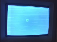
I measured the voltage at C12 and did indeed obtain a 9us long pulse. When I swapped out Q2, the foldover width reduced by half so only makes up a small proportion of the screen now. I tried turning up the brightness and the scan lines do extend off the right side, hopefully you can see it in the picture.


apm
Well-known member
Interesting and rather unexpected result. The lines off the right side suggest that the timing of the HSYNC pulse, rather than the length of the retrace period, is the problem. It looks like retrace is starting too late so it isn't finished by the time the next video line starts.
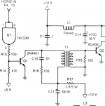
I might start with the base driver circuitry for Q2:

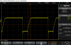
When Q2 is on, charge is stored in its base which needs to be pulled out for Q2 to turn off. That's the function of Q1 and transformer T1. If for whatever reason this circuit was limping along at half-power, Q2 would take too long to turn off and the retrace would start late. The signal at the base of Q2 should look something like this:

The vertical scale is small, 1V/div. During retrace you should see a negative pulse of -2V or so. The rest of the time it should be positive, around .6V or .7V (when Q2 is on). Turning on is gradual (sloping line), where turning off is fast. This plot was taken with just a resistor as load on Q2 rather than the yoke, so I'm not sure yours will look exactly the same, but it may be similar. If the turn-off is slow or the negative pulse is particularly narrow I might be suspicious.
On the other hand you could just replace Q1 and see if it helps. Check around this area and make sure there are no other obvious problems like bad solder joints, and double-check the resistance of R17. It's possible T1 has failed but you won't find a replacement without a parts donor analog board.
You could also try comparing signals on P4 pin 10, U1 pin 3 and the collector of Q1. They should all have approximately the same signal (HSYNC), variously inverted and level-shifted.
The odd part of the scan lines picture, though, is that the scan range is shifted off to the right on average (since it goes further to the right than the left). Did you manually recenter the image when you started? If not, that would mean there's a DC current through the yoke pushing it off centre. C15 is supposed to block DC current, so I'm not sure how that would happen.
I might start with the base driver circuitry for Q2:

When Q2 is on, charge is stored in its base which needs to be pulled out for Q2 to turn off. That's the function of Q1 and transformer T1. If for whatever reason this circuit was limping along at half-power, Q2 would take too long to turn off and the retrace would start late. The signal at the base of Q2 should look something like this:

The vertical scale is small, 1V/div. During retrace you should see a negative pulse of -2V or so. The rest of the time it should be positive, around .6V or .7V (when Q2 is on). Turning on is gradual (sloping line), where turning off is fast. This plot was taken with just a resistor as load on Q2 rather than the yoke, so I'm not sure yours will look exactly the same, but it may be similar. If the turn-off is slow or the negative pulse is particularly narrow I might be suspicious.
On the other hand you could just replace Q1 and see if it helps.
You could also try comparing signals on P4 pin 10, U1 pin 3 and the collector of Q1. They should all have approximately the same signal (HSYNC), variously inverted and level-shifted.
The odd part of the scan lines picture, though, is that the scan range is shifted off to the right on average (since it goes further to the right than the left). Did you manually recenter the image when you started? If not, that would mean there's a DC current through the yoke pushing it off centre. C15 is supposed to block DC current, so I'm not sure how that would happen.
Last edited by a moderator:
techknight
Well-known member
Rather strange result indeed.... But analog monitor circuitry odd failures never surprise me anymore, compared to what I saw in the old school projection TV world.
Elfen
Well-known member
Have you tried the width adjustment? Maybe in swapping Q2 the problem is fixed? If not, of course, more parts need to be swapped. C12? Q1 maybe? U1 perhaps, as that's part of the Horizontal circuit? I wish I had a full schematic to look over.I measured the voltage at C12 and did indeed obtain a 9us long pulse. When I swapped out Q2, the foldover width reduced by half so only makes up a small proportion of the screen now. I tried turning up the brightness and the scan lines do extend off the right side, hopefully you can see it in the picture.
I can imagine the worse you have seen.Rather strange result indeed.... But analog monitor circuitry odd failures never surprise me anymore, compared to what I saw in the old school projection TV world.
MacinPosh
Active member
apm - yes I did manually adjust the image centering, purely because when the brightness wasn't all the way up, you'd think the image wasn't central. Easy enough to put back.
Elfen - since replacing Q2, I have tried adjusting the width to no great success, the foldover persists. I can try swapping out more parts from my donor board no problem.
I haven't had much time this week to fiddle with the Mac, hopefully i'll get a chance this weekend and post the results ASAP.
Elfen - since replacing Q2, I have tried adjusting the width to no great success, the foldover persists. I can try swapping out more parts from my donor board no problem.
I haven't had much time this week to fiddle with the Mac, hopefully i'll get a chance this weekend and post the results ASAP.
MacinPosh
Active member
I have now replaced and adjusted a number of components as suggested, but unfortunately the foldover persists. I don't have much time to devote to this project at the moment, so i'll have to let it be until a later date. Hopefully some of the issues raised here may be useful to someone else.
One thing i've noticed is that the brightness potentiometer on the front of the analog board now seems more sluggish to change brightness?
One thing i've noticed is that the brightness potentiometer on the front of the analog board now seems more sluggish to change brightness?
Similar threads
- Replies
- 0
- Views
- 71
- Replies
- 4
- Views
- 247
- Replies
- 4
- Views
- 323
