• Updated 2023-07-12: Hello, Guest! Welcome back, and be sure to check out this follow-up post about our outage a week or so ago.

Mac SE - Third of screen blurry/lines on screen

MacinPosh

Active member
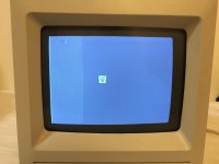
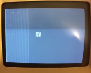
I recently bought and repaired a Mac SE - but whenever it boots, about a third of the screen is blurry. I assumed it was a logic board problem, but testing both the SE board in an SE/30 (which worked fine) and the SE/30 board in the SE (which produced the lines) revealed that it's actually an analog board issue. I've already replaced any leaky caps to no avail.

Any ideas?

FullSizeRender 2.jpg


aladds

Well-known member
Looks like the centering rings have been knocked, since the cursor image is backwards. Might be worth giving them (and the h/v size) adjustments a twiddle.

Remember your gloves! (Damn CRTs...)


techknight

Well-known member
Nope...

This is horizontal fold-over. Either the width coil has been turned too far, or more likely, the capacitor right next to it, 3.9UF? I cant recall. IS bad.


Elfen

Well-known member
To clarify Techknight's answer - the problem is on the Analog Board. Like he said, it is either the Width Coil or the cap next to it.

In adding, sometimes somebody turns the width coil too much of too hard and the ferrite core pops out or breaks. Many times somebody will use a screwdriver on it and that will shatter the ferrite core giving you such a problem like this. DO NOT USE A SCREW DRIVER! GET PLASTIC "TV TUNING" TOOLS TO TURN THAT COIL!


MacinPosh

Active member
Thanks for the quick responses. The ferrite core appears intact. I'll replace the 3.9uF cap and see if it makes a difference


MacinPosh

Active member
I've tried replacing the 3.9uF Cap and adjusting the width coil, but there's no improvement. It just pushes the problem left and right across the screen.

Any other ideas?


techknight

Well-known member
I am out of ideas. could be anything at this point. Flyback, Yoke, capacitors in the yoke circuit. etc... 


Elfen

Well-known member
There's a Horizontal positioning pot you can try to adjust. Tried that? (Should be a vertical one above that.)


Elfen

Well-known member
CENTERING THE SCREEN QUESTION:

The visible display has moved to the left of the screen area, but I don't see any adjustments for this anywhere. I know how to take the case off, and I can see all the adjustments, but no adjusting moves the display back to the center.
Should any of the visible adjustments (four pots) make the display move back to the center? If so, which one?
ANSWER 1: No. This extremely dangerous operation is accomplished by rotating the two metal rings on the back of the CRT. These rings are usually glued together and they move the image diagonally. By adjusting the two diagonals one can achieve the desired position.

The rings will need to move separately in order to adjust them, so the dab of paint that glues them together will need to be cracked (this can usually be accomplished by just rotating the rings, but sometimes they will have to be gently pried apart). Let me repeat this is a very dangerous adjustment as it is impossible to do with the machine off and the tabs on the rings are within millimetres of 9k volts. The preferred method is to rotate the rings with a non-conductive probe (laymen call these unsharpened pencils or plastic pen barrels.

ANSWER 2: I don't think any of the 4 pots are going to accomplish what you're wanting. There's also an adjustment on the yoke of the CRT, just in front of the small video board that plugs into the back of the CRT. If you look closely there should be a small lever/arm that you can move. As you move this, the alignment of your CRT video should also move right/left. Since this area is right in the middle of some high voltage and has to be done with the system/CRT on, it's not exactly something for the faint of heart or inexperienced to attempt.
From: http://www.ccadams.org/se/screen.html

Try Answer 1 but be careful! Even if you adjust the rings so you end up with the screen higher than "normal" you can lower it with the pot on the analog board.

 
Last edited by a moderator:

Paralel

Well-known member
I agree with TK, looks like foldover to me, but what you did should have fixed that. Strange.


Elfen

Well-known member
I think Alladds is right since the display is both to the left and down. Twisting them slightly will bring it up and to the right. Then adjust as needed with the pots and core.

Sorry Alladds, I did not read your post and missed it altogether.


TimHD

Well-known member
Found this post about adjusting the magnets to fix some screen issues elsewhere (indeed, I stumbled into the 68kmla Flickr site - no action in 3 years! - probably more a reflection of Flickr than 68kmla!). While this may not impact the foldover of the image on the monitor, it might help fix the screen's display which appears to be slightly tilted downward to the right, at the bottom edge. Anyone up for some magnet tweaking!

https://www.flickr.com/photos/66071596@N00/2304506276/in/photostream/

SE/30 Magnets on Yoke

Four magnets can be seen in this photo (there are 8 total), protruding tips painted in pink, surrounding the CRT yoke. Twisting these magnets alters the screen shape. When twisted clockwise, the topmost center magnet elevates the top-left section of the screen and shifts down the top-right section of the screen. After adjusting one magnet you will likely have to adjust others to make the screen alignment look correct. Special thanks to Tom Lee for the tip on adjusting these magnets to resolve screen distortion problems.

 
Last edited by a moderator:

Elfen

Well-known member
It's not those Magnets, TimHD unless a couple of them are missing from the yoke. Its the position of the yoke and magnet assembly and that is controlled by the rings. Twisting those magnet will distort the screen as they are set to keep it in its square shape.

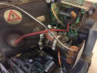
A picture of the section by MacinPosh would be great.


apm

Well-known member
The problem is definitely foldover, and the reason is that, for whatever reason, the horizontal retrace is happening too slowly. The retrace speed is determined by the inductance of the yoke, capacitor C12, and the inductance/capacitance of the flyback transformer.

The yoke is probably fine since the rest of the picture looks fine, so concentrate on the other two. Of those, the flyback is the more likely failure but C12 is easier to replace, so start with that. :) It should be 0.033uF (maybe slightly different on some models), and I would use a part rated at 250V, or more if it's labelled that way on the part you're replacing.

What normally happens is that when a line of video finishes, the HSYNC pulse goes low and transistor Q2 switches off. At that point, the beam is at the right-hand side of the screen and there's several amps of current going through the yoke. When Q2 turns off, that current charges up capacitor C12, in the process moving the beam back to the left side of the screen for the next line. That whole process is supposed to finish well before the next video line starts, but if C12 (or the parasitic capacitance of the flyback) is too large, the retrace will happen too slowly and the next line of video will start before the retrace has finished.

It shouldn't be related to the positioning of the yoke or the magnets. There are a few other possible failure points on the analog board but C12 and the flyback seem like the most likely.
 

CelGen

Well-known member
I am thinking flyback, its probably on its way out. 
Except that's foldover we're seeing, so it's a horizontal issue.

Regarding the centering magnets, if they show no indication of being disturbed in the last....I dunno 25 years? Don't bother touching them. The rotation of the screen is more the yoke itself shifted at some point but that shouldn't really affect the horizontal deflection that badly. That's a solid indication that something about the horizontal deflection circuit is faulty. Verify your adjustments with the horizontal centering and width coils.

 
Last edited by a moderator:

MacinPosh

Active member
Thanks for all the replies. I've tried replacing C12 (with some caps that I accidentally ordered, but happened to be the correct value), and I've given the coils more adjustments to no avail. I'm sure that the yoke isn't the problem, as I've tested the analog board in another machine with and it still produces the lines. Is it worth me ordering a replacement flyback to see if that fixes the issue? Unless someone happens to have a spare they don't need?

IMG_7319.JPG

IMG_7320.JPG


Elfen

Well-known member
Chasing a wild goose here...

Get some cloth measuring tape (like from a sewing kit) and measure that floppy disk icon.

Why? OK, hear me out.

- The Mac's resolution is supposed to be 1/72nd of an inch per pixel.

- That Flashing Disk Icon is 32 X 32 pixels. This would make the icon (doing the math...) .444th inches or 4/9th inches (just a tiny bit over 7/16th inches) square.

- If it not a bit over 7/16th inches square, you need to adjust the screen's height and width before adjusting its horizontal/vertical position. This is done at a couple of pots near the horizontal & vertical adjustment area.

If the screen is too wide, shrinking its width will lessen the fold over. After that you can adjust the horizontal position. The screen's width can be set to near maximum that it will fold over and no matter how you adjust the horizontal position it will never unfold.

There were a coupe of recent discussions about the height width of a 68K's screen. One of the links is here:

https://68kmla.org/forums/index.php?/topic/27020-se30-with-a-smaller-screen/?p=288235

But for you, you need to shrink the screen first, then adjust its position and then when the fold-over issue is gone, do tiny adjustments until it is right.

 
Top