• Updated 2023-07-12: Hello, Guest! Welcome back, and be sure to check out this follow-up post about our outage a week or so ago.

Lisa 1.8a PSU clone by Warmech

mvwijland

New member
I am building the Lisa 1.8a PSU Clone as designed by Warmech and I have a question. I have sourced all items as mentioned on the site: https://github.com/warmech/lisa-hardware/tree/main/LisATX - Pico ATX PSU Replacement

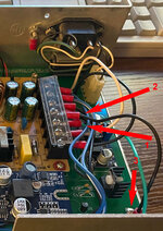
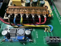
My question is, and i hope somebody has also created this replacement PSU, how to connect the Pico ATX to the board? Is it soldering the bottom of the pico ATX one-on-one to the board?

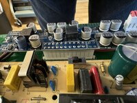
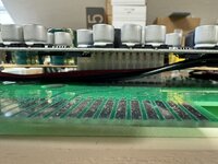
If any one as also created this power supply, i would very much appreciate a number of pictures? Also of the components that are covered by the Pico ATX/
 

macmike

Member
Hi, yes i build this clone too. I put in a ATX-Connector (male) in the big PCB. Then you have to desolder the two ATX Connectors out of the Pico ATX and put in the big one from the opposite side. The 4-Pin connector is useless.
I will send you some pictures tomorrow.

Regards,Michael
 

mvwijland

New member
Hi, yes i build this clone too. I put in a ATX-Connector (male) in the big PCB. Then you have to desolder the two ATX Connectors out of the Pico ATX and put in the big one from the opposite side. The 4-Pin connector is useless.
I will send you some pictures tomorrow.

Regards,Michael
Great, thanks, pictures much appreciated.
 

macmike

Member
Hi,

i must correct my answer. I changed the connector in the Pico-ATX because it don´t fit in the one i used on the Lisa-PCB.
Please take a look at the pictures.

Regards, MichaelLisaPS1.jpg
 

Attachments

  • LisaPS3.jpg
    LisaPS3.jpg
    343.3 KB · Views: 39
  • LisaPS2.jpg
    LisaPS2.jpg
    278 KB · Views: 40

mvwijland

New member
Oke, great, this helps me a lot. I will finish the power supply. and hopefully the Lisa will come back to live.
 

mvwijland

New member
@macmike
Hi,

i must correct my answer. I changed the connector in the Pico-ATX because it don´t fit in the one i used on the Lisa-PCB.
Please take a look at the pictures.

Regards, MichaelView attachment 72248
Thanks MacMike for helping me out. I just finished building this PSU and tested the 33, 5, -5, 12 -12 rails and all looks good.
But then I checked the schematic and saw a -100V and +300V.

Are these currents that come from the videoboard in the Lisa?
 

stepleton

Well-known member
But then I checked the schematic and saw a -100V and +300V.

Are these currents that come from the videoboard in the Lisa?
Those are for video focus and contrast. The Lisa PSU does not make them --- those voltages just go into the PSU, pass through a pair of potentiometers that stick out the back of the Lisa so that the user can make an adjustment, and then they go right back out of the PSU. It's wholly unrelated to anything else the PSU does and there is no electrical connection to the "regular" PSU bits.

I'm sure the good folks at DataPower got a chuckle out of it when they first saw this as part of the spec for the 1.8A supply.
 

anotherLISAguy

New member
Considering this as a backup - thought I would check in and ask how they are holding up. The soldering/assembly seems very straightforward so I was curious what the component costs worked out to be - the pcb looks fairly straightforward with companies like PCWay.
Any input is appreciated.
 

AppleTree

Member
I am about to build this as well. Just ordered PCBs from JLCPCB. I've read Warmech's github page and assembly process seems straightforward. However I've noticed a couple of discrepancies between the instructions and the finished product picture there. Please see the attached photo.

* Instruction No 7 says you need to connect S-180-12 ground to the frame ground pad next to the molex connector but Lisa PSU's frame ground is not connected to the molex connector. In fact, Warmech seems to have done something different, You can see that the green ground wire (that is connected to S-180-12 PSU) goes to the other side of the molex connector (noted as 1 in the attached photo). I presume it is attached to the frame ground somewhere, but not sure why he did not connect it directly to ground wire coming from the mains. That's what I will do.

* Instruction No 6 says to connect S-180-12's DC output to Pico's power input, which seems straight forward enough (to supply +12V to Pico). But in the photo, I noticed that one of the black wire splits into two (2 in the photo) and one end is connected to the PCB (3 in the photo). I am not sure what that's doing, as there is no place on the PCB for this wire to go to. I will probably forget about the connection between S-180-12's DC ground and PCB.

Unfortunately @macmike's photos do not show this area so I can't tell what he's done for above points.
 

Attachments

  • psu-1.jpg
    psu-1.jpg
    458.9 KB · Views: 19

macmike

Member
Hi, here a some more pictures from two units i build. Hope it helps.

Regards, Michael
 

Attachments

  • LisaPS7.jpg
    LisaPS7.jpg
    433 KB · Views: 17
  • LisaPS6.jpg
    LisaPS6.jpg
    423.6 KB · Views: 13
  • LisaPS5.jpg
    LisaPS5.jpg
    524.2 KB · Views: 12

AppleTree

Member
Hi, here a some more pictures from two units i build. Hope it helps.

Regards, Michael
Thank you very much for the photos @macmike. You did exactly what I am going to do. That is, to connect frame ground pad on PCB directly to the ground on the mains, and don’t worry about splitting one of the S-180-12’s DC ground connections into two.
 
Top