• Updated 2023-07-12: Hello, Guest! Welcome back, and be sure to check out this follow-up post about our outage a week or so ago.

Joystick mouse replacement for Lisa/128/512/Plus

cheesestraws

Well-known member
I almost forgot to consider getting this. Do you confirm it's essential and you didn't jerry-rig something yourself?
Yup, you need a serial adapter thing.  I got a cheapish one off eBay.

Did you go that route? 
I didn't, but it'd be totally different for a mouse anyway.  I agree it would make things much easier...

 
Last edited by a moderator:

Mu0n

Well-known member
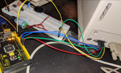
Still waiting for my parts, but I started some progress with my ATMega arduino board and checking out your mouse code.

I believe the only difference I needed for the Plus is to reverse the boolean on the mouse click output. You used a pullup input and it was constantly trying to eject the disk drive when I first plugged it in. Reversing it did the trick.


image.png

 
Last edited by a moderator:

cheesestraws

Well-known member
reverse the boolean on the mouse click output
... you're right, that ought to be active-low and I'm treating it as if it was active high.

... ... why is mine working? :D

edit: because on mine the switch is wired between the input (with pullup) and ground, not 5v.  So when the switch is inactive, the pin reads high, and when it's pressed the pin reads low.  There's no pulldown internally on the boards I have.  So if I had the switch between 5v and the pin, I'd get random mouse clicks from whatever random noise happened to be around while I was debugging it - usually my hand accidentally prodding the solder joints.  I'd suggest doing as I did and making that input active-low and grounding it with the switch.

 
Last edited by a moderator:

Mu0n

Well-known member
image.png

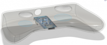
This is my first Fusion360 project so I'm FOR SURE, overthinking a few things in it. Here are my steps and wants:

-Added an image of the Arduino micro 5V I ordered (order still en route) where I tried using the website's image provided in a shot that also had an american quarter, so I deduced the dimensions as best I could

-The general size of the controller is very slightly smaller than an xbox360 controller and it's pretty silly since it'll have the one button

-the button hole on the right is only temporarily sized, I have no idea yet which of the button types I'll be using

-same for the stick hole, I'm waiting to receive my analog sticks to decide how large to make it

-I have 3 little "walls" to prevent the board to wiggle out. I made such little gaps around it and I'm thinking about giving it more space but I have no experience on how much is enough and how much is too much

-the arduino board gives 3 mounting holes which I made little riser posts for it (still need to do a larger part of the post undernearth the board).

-the hole in the back will attempt to be of the proper size for some cable securing nut-thing I got off digikey

-hole in front for the micro-usb connector that comes with the board, I'm only guesstimating the size right now

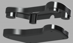
-one of the last steps I'll do is to split the top and bottom half of this thing so that they can be printed separately so that I can properly assemble it anyway.

-dunno which button I'll use, I need to have them in hand to decide based on ClickFeel

-I might be forced to get rid of the concave aspect of the outer shell underneath it, because it would just be too hard to 3d Print. It's a bummer, unless some of you have an idea

You can check out and move around the model with this public link: https://a360.co/2X7DvxZ

Parts ordered status:

-10x small clicky buttons from Amazon (received): https://www.amazon.ca/-/fr/gp/product/B07FKB6648/

-3x Adafruit 5V Trinket 16 Mhz from BuyaPi.ca (en route): https://www.buyapi.ca/product/adafruit-pro-trinket-5v-16mhz/

-3x Analog sticks (en route) from BuyaPi.ca: https://www.buyapi.ca/product/analog-2-axis-thumb-joystick-with-select-button/

-1x 16 mm illuminated green button from BuyaPi.ca (en route): https://www.buyapi.ca/product/16mm-illuminated-pushbutton-green-momentary/

-1x ?? mm red button (en route) from BuyaPi.ca: https://www.buyapi.ca/product/3a-125v-momentary-push-button-switch/

-2x cable glands (received) from DigiKey: https://www.digikey.ca/en/products/detail/bud-industries/IPG-2227/5291485

-2x DB-9 cables (en route) from monoprice: https://www.monoprice.com/product?c_id=301&cp_id=30112&cs_id=3011201&p_id=442&seq=1&format=2

 
Last edited by a moderator:

cheesestraws

Well-known member
You can check out and move around the model with this public link: https://a360.co/2X7DvxZ
This is much classier than my "case"—I like it a lot!

-hole in front for the micro-usb connector that comes with the board, I'm only guesstimating the size right now
At least for me, with a Pro Mini, it could run perfectly comfortably off the current from the mouse port (at the same time as a Floppy Emu, so).  In fact, my Minis don't have a USB port at all, they use a separate breakout board for USB.  Though you might need it for the keyboard side of your project...


Mu0n

Well-known member
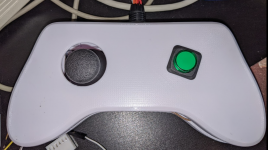
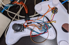
Got my stuff (except the DB-9 cable) and a prototype is working!

The caption for this video is:

"Confinement Day 75"


Mu0n

Well-known member
I'm about to send my STL file to a friend so he can start the 3d printing for me. 

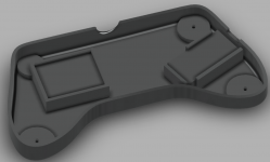
Check it out: assembly with 4 screws. I'm hoping the holes are big enough for the button and stick.

in-browser model viewer:

https://a360.co/2X7DvxZ

Side analysis:


Mu0n

Well-known member
First iteration's problems:

-stick is a smidge too high and will cause friction with the opening's edges

-the cylinder riser pins broke very early and just can't be used, and the risers themselves broke off after minimal lateral force

-the cable hole was too small

-I think the back and front cable holes could just be improved if the middle separation goes to their centers

-the arduino's placement is just bad in the dead center, it creates too many problems during assembly with the cables I have.

-I need to find a way to create one 4-way node and one 5-way node. I don't have those simple through-hole breadboards, so....solder wires "in the air"?

Link towards revised version:

-fat cylinders for screws 

-"cradle" + glue approach instead of risers to hold the pcbs

-arduino on the side instead of center

https://a360.co/2X7DvxZ

image.png

image.png


Mu0n

Well-known member
I should be getting my DB9 cable today, as well as some very needed heat srink cable tubes. 

image.png

image.png


Mu0n

Well-known member
Moving on to the next gamepad that would use the 4C4P RJ11 cable, replacing a keyboard. I've quoted the appropriate section of Inside Macintosh but I'm at a loss of how to make it work in Arduino.

I admit I don't know that much about the arduino architecture.

-I imagine I need to use digital pins and not analog pins, since I only need to create 5V pulses to create the bits.

-at 9600 bps, we get 104 microseconds at the smallest unit of change, but we need control over creating data pulses that happen 40 microseconds before the clock pulse ticks, so I must use a faster speed?

-so far, all the arduino code I've seen configures GPIO pins as either WRITE or READ. But Inside Macintosh clearly says the data wire needs to be able to send and receive both according to its unique specific protocol. How do I set this up in Arduino?

I found this website that sheds some light on setting up communications with another board (outside of the arduino ecosystem), but it looks pretty similar:

http://www.synack.net/~bbraun/mackbd/index.html 


cheesestraws

Well-known member
I imagine I need to use digital pins and not analog pins, since I only need to create 5V pulses to create the bits.
Yup.

at 9600 bps, we get 104 microseconds at the smallest unit of change, but we need control over creating data pulses that happen 40 microseconds before the clock pulse ticks, so I must use a faster speed? 
No idea.  I'd be inclined to suggest thinking of this as a timing problem rather than as a "bits per second" problem, though.  Timers are probably your friend here.

so far, all the arduino code I've seen configures GPIO pins as either WRITE or READ. But Inside Macintosh clearly says the data wire needs to be able to send and receive both according to its unique specific protocol
You can switch a pin between read and write as you need, it's not a one-time initialisation.  If you look at bbraun's code (which you linked), the data line is switched between IN and OUT (main.c line 201, for example) depending on whether the board is reading from it or writing to it.


Mu0n

Well-known member
 I also revisited your mouse code yesterday.

What I'm experiencing:

-cursor movement is somewhat a little slow during normal operation, but it's ok

-when in combat in Archon, mouse scrolling speed has no impact - the game only detects the direction of movement and the characters move to some pre-planned speed according to the game rules

-It's very hard to go into purely horizontal or vertical directions with a deadzone of 30. Most of the time, diagonal movement is done and it forces me to fight with these lines of approach and throws away pure horizontals and verticals. Kind of like in real life with a physical mouse, but even worse

So, I played around with the code a bit, and did:

-push up the minimal movement threshold to 40 instead of 30

-first check that a direction is dominating (dominating threshold of 200) WHILE the other IS NOT dominating to only push for a movement in that solo dominating direction; then check the other with an else if

-when no direction is dominating, do what was done initially, which is allow both directions to act at the same time

What I get is noticeably better in Archon combat (I'm able to hit those x-only and y-only shots more often), but noticeably worse during normal cursor operation: I get feeble movement whenever both directions are involved. I get slightly faster movement when only one direction is involved. The strangest thing is that I can still get a small movement in the non-dominating direction.

Code:
// The quadrature phases to output
const bool waveform1[] = {HIGH, LOW, LOW, HIGH};
const bool waveform2[] = {HIGH, HIGH, LOW, LOW};
const int doNothingTolerance = 40; //no movement if you don't reach this miminal threshold
const int pureDirectionTolerance = 200;  //if a direction has that, but the other doesn't, lock it in the direction that has it

int xGPIOs[] = {6, 5};
int yGPIOs[] = {4, 3};
const int xAnalogue = 3;
const int yAnalogue = 2;

const int clickOutGPIO = 10;
const int clickInGPIO = 11;

// Two digital outputs set permanently to high and low, respectively, to reference
// the variable resistors with 
const int hiRefGPIO = 13;
const int loRefGPIO = 12;

// the timestamps (in milliseconds) when the axis last was updated
unsigned long xTimestamp = 0;
unsigned long yTimestamp = 0;

// the indexes into the waveforms
int xIdx = 0; 
int yIdx = 0;

int xIsStill() {
  return analogueValueIsStill(analogRead(xAnalogue));
}

int yIsStill() {
  return analogueValueIsStill(analogRead(yAnalogue));
}

long xDelay() {
  return analogueValueToDelay(analogRead(xAnalogue));
}

long yDelay() {
  return analogueValueToDelay(analogRead(yAnalogue));
}

int xDirection() {
  return analogueValueToDirection(analogRead(xAnalogue));
}

int yDirection() {
  return analogueValueToDirection(analogRead(yAnalogue));
}

int xShouldAdvance() {
  unsigned long now = millis();
  // if the joystick is in the "still" region, don't update
  if (xIsStill()) {
    return 0;
  }
  
  if ((xTimestamp + xDelay()) < now) {
    xTimestamp = now;
    return 1;
  } else {
    return 0;
  }
}

int yShouldAdvance() {
  unsigned long now = millis();
  // if the joystick is in the "still" region, don't update
  if (yIsStill()) {
    return 0;
  }
  
  if ((yTimestamp + yDelay()) < now) {
    yTimestamp = now;
    return 1;
  } else {
    return 0;
  }
}

int xIsWellEstablished() {
     unsigned long now = millis();
  // if the joystick is in the "dominating" region
  if (analogueValueIsDominating(analogRead(xAnalogue))) {
    return 1;
  }
}


int yIsWellEstablished() {
     unsigned long now = millis();
  // if the joystick is in the "dominating" region
  if (analogueValueIsDominating(analogRead(yAnalogue))) {
    return 1;
  }
}

void dealWithButton() {
  int btn = digitalRead(clickInGPIO);
  digitalWrite(clickOutGPIO, btn);
}

int analogueValueIsStill(int value) {

  if (value > (512 + doNothingTolerance)) {
    return 0;
  }
  if (value < (512 - doNothingTolerance)) {
    return 0;
  }
  
  return 1;
}

int analogueValueIsDominating(int value) {

  if (value > (512 + pureDirectionTolerance)) {
    return 1;
  }
  if (value < (512 - pureDirectionTolerance)) {
    return 1;
  }
  
  return 0;
}

int analogueValueToMagnitude(int value) {
  return abs(value - 512);
}

int analogueValueToDirection(int value) {
  if (value < 512) {
    return -1;
  }
  return 1;
}

long analogueValueToDelay(int value) {
  const long minDelay = 4;
  
  long mag = analogueValueToMagnitude(value);

  return ((512 - mag) / 32) + minDelay;
}

void writeQuadrature(int gpios[], int idx) {
  digitalWrite(gpios[0], waveform1[idx % 4]);
  digitalWrite(gpios[1], waveform2[idx % 4]);
}


void setup() {
  Serial.begin(9600);
  
  // set up quadrature outputs
  pinMode(xGPIOs[0], OUTPUT);
  pinMode(xGPIOs[1], OUTPUT);
  pinMode(yGPIOs[0], OUTPUT);
  pinMode(yGPIOs[1], OUTPUT);
  pinMode(clickInGPIO, INPUT_PULLUP);
  pinMode(clickOutGPIO, OUTPUT);

  pinMode(hiRefGPIO, OUTPUT);
  digitalWrite(hiRefGPIO, HIGH);
  pinMode(loRefGPIO, OUTPUT);
  digitalWrite(loRefGPIO, LOW);

  digitalWrite(xGPIOs[0], HIGH);
  digitalWrite(xGPIOs[1], HIGH);
  digitalWrite(yGPIOs[0], HIGH);
  digitalWrite(yGPIOs[1], HIGH);
  digitalWrite(clickOutGPIO, HIGH);

  Serial.print("initialised...\n");
}

void loop() {
  dealWithButton();
  
  //clear cut x movement only
  if (xShouldAdvance() && xIsWellEstablished() && !yIsWellEstablished()) {
    xIdx = (xIdx + xDirection()) % 4;
    if (xIdx < 0) { xIdx += 4; }
    writeQuadrature(xGPIOs, xIdx);
    return;
  }
  //clear cut y movement only
  else if (yShouldAdvance() && yIsWellEstablished() && !xIsWellEstablished()) {
    yIdx = (yIdx + yDirection()) % 4;
    if (yIdx < 0) { yIdx += 4; }
    writeQuadrature(yGPIOs, yIdx);
    return;
  }
  
  //weak x
  if(xShouldAdvance()) {
   xIdx = (xIdx + xDirection()) % 4;
    if (xIdx < 0) { xIdx += 4; }
    writeQuadrature(xGPIOs, xIdx);
  }
  //weak y
  if(yShouldAdvance()) {
   yIdx = (yIdx + yDirection()) % 4;
    if (yIdx < 0) { yIdx += 4; }
    writeQuadrature(yGPIOs, yIdx);
  }


  // DEBUG:
  //Serial.print("x: ");
  //Serial.print(analogRead(xAnalogue));
  //Serial.print("y: ");
  //Serial.print(analogRead(yAnalogue));
  //Serial.print("button: ");
  //Serial.print(digitalRead(clickInGPIO));
  //Serial.print("\n"); 
}
 
Top