• Updated 2023-07-12: Hello, Guest! Welcome back, and be sure to check out this follow-up post about our outage a week or so ago.

IIci etc. ATX to 10pin Adapter

Phipli

Well-known member
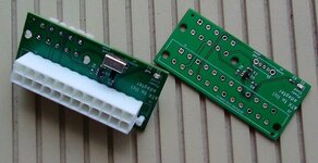
A friend designed an adapter for converting ATX to connect to a IIcx, IIci, IIsi, Q700, C/Q650, IIvx, IIvi, P600, Q800 and 7100. Handy for bench testing, and with a little work on mounting, may help with replacing PSUs.

He has shared the design. You're free to make some for yourself.

I've asked him to clarify licencing. I'd assume non commercial for now :)


MrFahrenheit

Well-known member
A friend designed an adapter for converting ATX to connect to a IIcx, IIci, IIsi, Q700, C/Q650, IIvx, IIvi, P600, Q800 and 7100. Handy for bench testing, and with a little work on mounting, may help with replacing PSUs.

He has shared the design. You're free to make some for yourself.

I've asked him to clarify licencing. I'd assume non commercial for now :)


That's great!!!
 

mrw

Member
Thanks so much for sharing this! I've ordered 5 boards from JLCPCB and the requisite parts from DigiKey. If I can get one to work with my Quadra 650, I'll use two more for my IIcis.

I'll post my experience here when I've got a build done!
 

olePigeon

Well-known member
I'm an idiot. I clicked through all the shipping options and found the economy month-long shipping. Fine with me. :)

With the coupon, it was just $11 total (including the shipping, parts, & assembly) for 5 pre-assembled PCBs. I'm gonna salvage the Molex connectors from ewaste. Never occurred to me that those would be the expensive part.
 

Melkhior

Well-known member
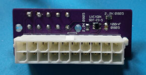
I have just put my own take on that idea on GitHub.
I'm using a 4-layers board & 0603 components, made/soldered by JLCPCB.
I have a small LED connected to the ATX 'power good' signal to see if power is supplied.
And a small switch that connect the ATX 'power supply on' signals to either the soft-power circuitry, or to ground to force-start the power supply. Helpful for system with a dodgy soft-power circuitry. I actually haven't tested the soft-power as my IIci soft-power is dead (tested with the known-good power supply of my Quadra 650).
Didn't cost too much, got 5 back from JLCPCB for about 25 euros shipping/custom/discount included (so quite a bit more expensive than the two-layers version!). The two connectors and switch I got from Mouser, not absurdly expensive, probably 9-10 euros per set. But you need to buy a lot of stuff in one go from Mouser to get free shipping :-(
Edit:
Picture.jpg
 
Last edited:

pdyholman

Member
Really useful! If anyone is planning to have boards made, I'm happy to buy one or two if it helps reduces your costs !
 

Phipli

Well-known member
@Melkhior Yeah, who would've thought those connectors would be so expensive. I guess it's the price we pay to support a monopoly. :/
Look pretty cheap to me ;)


£1.50 for 5, plus £1.06 shipping, plus tax.

I've had much more trouble with the 2x5p ones.

EDIT/Warning: The linked 2x10 connectors will not fit the original PCB as their pins are slightly differently located. There is an updated "alternative" version of the files which are identical, except they are designed to accommodate both connector types (2x10). - 14th March 2023
 
Last edited by a moderator:

mrw

Member
I recently used the PCB that started this thread (https://github.com/GeorgeRudolf/OldMacATX) to replace the power supply in my Quadra 650.

Attached is a CSV of what I ordered from DigiKey for my build. Note that the listed parts and their quantities reflect that I received 5 PCBs that I opted to assemble myself.

In particular, for the 20 pin ATX-side connector, I used Molex part number 0039299206:

It's a little steep at $3 USD but at least it was available to ship!

Here's what I ended up with:

oldmacatx-front.jpg

I attached my assembled PCB to a Mini-Box 80-watt picoPSU:


This is probably a little under-powered for a Quadra 650 as I understand its original power supply put out ~100 watts. However, it seems to be fine for mine: it never had a CD-ROM drive, and I removed its hard drive and put a ZuluSCSI where its floppy drive used to be.

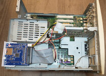
Here's what it looks like installed:
oldmacatx-installed.jpg

Soft power from the keyboard works as promised, though with the picoPSU it takes about a second.

My previous soldering experience has been limited to basic recapping and reflowing. This was the first PCB I assembled and the first time I worked with such small surface mount components. Here are some notes that other novices may find useful:
  • The capacitors recommended in the GitHub README are ceramic and therefore unpolarized. The board doesn't indicate which pad is positive because it doesn't matter.
  • Setting my soldering iron to a temperature of 562°F/~295°C made me less likely to destroy the surface-mount components, in particular the capacitor.
  • A temperature of 662°F/350°C made it easier for me to solder the Molex connectors.
The GitHub README claims that this board is "foolproof". I agree! Thanks so much for sharing this, @Phipli

@Melkhior your board looks great - I like the addition of the LED in particular. I'll let you know when I'm able to build one of yours.
 

Melkhior

Well-known member
@mrw For mine, beware that the passive are 0603, even smaller than 0805 (the LED is 0805), it's designed to be soldered by JLCPCB rather than me :) The Kicad project is there in GitHub as well, so you could replace the passive by larger version if you wanted to. I'm also using weaker (higher resistance) pull-up/down resistor (4.7K vs. 2.2K I think) for not particular reason, so what you have now works for you you might want to stick with that.
My Molex parts were 15-24-7100 and 39-29-9246, I have no idea what the differences are - I went for cheap and readily available...
 

olePigeon

Well-known member
Can the Pico be wired to mains directly? Oh, it's 12v. I'll poke around, maybe they make one that's designed to work like a normal PSU. I was thinking about 3D printing a bracket to hold the original plugs, then wire the Pico to the plugs. That way it'll look stock from the outside, but still have all that extra room for other hacks.
 

Phipli

Well-known member
Can the Pico be wired to mains directly? Oh, it's 12v. I'll poke around, maybe they make one that's designed to work like a normal PSU. I was thinking about 3D printing a bracket to hold the original plugs, then wire the Pico to the plugs. That way it'll look stock from the outside, but still have all that extra room for other hacks.
Be a little careful with picos, they need a powerful external power supply and they're generally less powerful than IIci PSU. Also, a lot of eBay listings are just out and out dishonest, exaggerating their capabilities. They're not really a solution for any computer this adapter is intended for, except perhaps the IIsi (I haven't checked the figures).
 

Jockelill

Well-known member
@mrw For mine, beware that the passive are 0603, even smaller than 0805 (the LED is 0805), it's designed to be soldered by JLCPCB rather than me :) The Kicad project is there in GitHub as well, so you could replace the passive by larger version if you wanted to. I'm also using weaker (higher resistance) pull-up/down resistor (4.7K vs. 2.2K I think) for not particular reason, so what you have now works for you you might want to stick with that.
My Molex parts were 15-24-7100 and 39-29-9246, I have no idea what the differences are - I went for cheap and readily available...
Interested in selling one of your surplus boards? Looks very neat! Of course I could just order one, but if you have surplus and it’s already in EU, it makes life easier :).
 
Top