• Updated 2023-07-12: Hello, Guest! Welcome back, and be sure to check out this follow-up post about our outage a week or so ago.

Help with LCII Repair

LaPorta

Well-known member
Hi everyone,

I have been working on a recap job for a forum member on their LCII board. It was in reasonable shape short of cap electrolyte all over as expected. I did the recap, everything went well. Fired up the board in a test stand, and it started up but had weird audio scratchiness, video issues, and would occasionally restart itself. I figured that the electrolyte probably made its way under a few on the nearby chips and shorted something. So, I removed UA10, U12, U9, and UB9. As expected, there was a lot of electrolyte under there that I cleaned, then resoldered the chips. This time, I got a completely clear bong when starting, but then got the ascending/descending chime of death. Reseated the VRAM SIMM (and tried without it), but that did not help. The only other chip that looked like it had a lot of electrolyte exposure was U10. So I remove U10, and it was somewhat stubborn, requiring probably 20 seconds of heat to lift off. There were a few deep ruts near some of the pins, and exposed traces as a result of the electrolyte that I cleaned up under there. I checked continuity where the breaks had occurred, and amazingly, everything checked out ok. So, I resoldered U10 into place. Now, when I start the board up, there is no bong, nothing. The LCD I have it hooked up to has an amber status light, which turns green, but no gray screen appears. Could I have somehow damaged U10, and how would I go about testing this? Looking at the Bomarc schematics, it appears that U10 is tasked with controlling parts of the RTC, disk controller, and the reset circuit, but other than that I am not sure how it would be causing this.

Is there anyone out there who might have some insight into this? So much for this just being about replacing caps...

 
Last edited by a moderator:

ZaneKaminski

Well-known member
Looking at the schematic briefly, it seems that U10 6805 microcontroller drives the system reset low, since the physical reset button on the LC II is hooked up to the 6805's reset input. I would check if the system reset (available on the PDS slot) is ever going high with a multimeter or something. If reset is always low that suggests that U10 is not working right.


bibilit

Well-known member
U10 is the infamous Egret Chip.

A lot has been said about it, won't be able to boot if traces or chip is bad.


LaPorta

Well-known member
Traces so far appear to be ok from what I can tell. Will try out your suggestion, Zane. If I need a replacement, where can one source these things, if at all?


LaPorta

Well-known member
I’ll recheck traces tonight. What could I expect on the reset pin with a scope if it works and if it doesn’t work properly? Also, I found a supposed source of replacements I could use. When mounting/dismounting these I don’t have a hot air nozzle exactly the size of the chip but close. Any suggestions about that?


LaPorta

Well-known member
For small chips, try this.  https://youtu.be/CVsmwFAkf7I?t=71 or for larger you could use solder removal alloy which is metal that melts at low temp and helps keep the pins hot.  
Interesting, but that looks like it would have even more chance of causing thermal damage than any hot air I fired at it. I keep my air at 350, a far cry from my irons usual 600-700. I have a bit more hope now this may be more of a trace issue.


Mr SN

Well-known member
I use the techniques in that video all the time.  I think you have more chance of causing collateral damage with hot air.  I used to use hot air and have since switched to using the soldering iron - the tip is also key to being successful.  I run my iron at 330C when removing SMDs.  


LaPorta

Well-known member
Thanks for the tip. I have a knife tip like that around somewhere. So I’m still 50-50 on whether or not the chip is gone :). Will have to see.


Mr SN

Well-known member
You bring up a good point I neglected, the condition of the chip probably needs to be considered.  Hot air may be better for delicate chips, as the soldering with flux will remove corrosion and possibly cause pins on the chips to break if they are frail.  Though, when soldering back on, you'd encounter the same.  I lost a 3080 chip on a LC motherboard using the solder method due to the corrosion.  I'm currently waiting for replacement chips to come from China.


ZaneKaminski

Well-known member
What could I expect on the reset pin
The system runs when reset is high (above 2.0 V) and doesn't run when reset is low (below 0.8 V). When the computer powers on, reset should be low, but then it should go high and that in turn causes the processor to work, startup chime, etc. So if it's always low or going back and forth, the Egret is resetting the system when it shouldn't be.

If I need a replacement, where can one source these things, if at all?
I don't think it'll be easy--the Egret MCU is not only a custom Apple chip, but there's a program inside that I don't think anyone has an image for, even if you could buy a similar blank microcontroller. So I think the only source is to pull it off of another LC II or Mac with the same chip.

thermal damage [from hot air reflow]
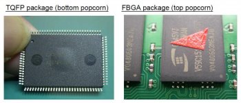
It's certainly possible. Moisture builds up in chips over time and when soldered with hot air, the water inside can boil quickly and expand, cracking the chip or otherwise deforming the package. This is called "popcorning." Here's a picture I found showing some extreme examples, but it's not necessarily visible from the outside:

Screen Shot 2020-08-10 at 11.17.26 AM.jpg

I didn't believe popcorning was a major issue until some time ago, when I made a batch of Commodore 64 geoRAM clones using an old CPLD chip. After reflow soldering in the oven, every single board failed. Baking the chips for a day at 100 degC fixed the issue in the next production run. So you've often gotta bake the chips/board before using hot air. The LC II board probably can't handle 100 degC so you can do 50 degC or something for longer. (next time, that is)

As for iron temperature, I don't think it's an issue. I typically use a Hakko FX-951 soldering iron at 800-840 degC. (Higher than 840 is technically brazing, not soldering.) Even at that high of a temperature, I don't think you end up holding the iron on the pins for long enough to heat the chip up enough to get the popcorning failure, since nobody talks about it with hand-soldering.

 
Last edited by a moderator:

Daniël

Well-known member
I don't think it'll be easy--the Egret MCU is not only a custom Apple chip, but there's a program inside that I don't think anyone has an image for, even if you could buy a similar blank microcontroller. So I think the only source is to pull it off of another LC II or Mac with the same chip.
EGRET ROM dumps are available online if you know where to look.

EDIT: One can also dump the EGRET of a working Macintosh with this utility: https://www.gryphel.com/c/minivmac/extras/egretrom/index.html

 
Last edited by a moderator:

ZaneKaminski

Well-known member
EDIT: One can also dump the EGRET of a working Macintosh with this utility: https://www.gryphel.com/c/minivmac/extras/egretrom/index.html
Wow! I did not know this. I thought it would not be possible to dump it from the Mac.

Maybe the Egret is the same as one of these 6805 MCUs, and if so, we could burn another: http://www.bitsavers.org/components/motorola/6805/Single_Chip_Microcontrollers.pdf

The Egret has 28 pins and evidently 4.25 kB of ROM, judging from the ROM dumps. None of the MCUs in that list seem to match. Some have 4.5 kB of ROM though. 


LaPorta

Well-known member
So far I buzzed out traces for pins 1-14 (one side, all I had time for) and so far it appears the traces are intact. However: I did not check 12 or 13: on the schematic, 12 leads to RESET (is that just an 030 pin?) and to some sort of delta with lines that I am not familiar with diagram-wise. That makes me lean towards the EGRET. I found this possible supply of them, but I am not sure if it it the usual Chinese knockoff stuff. I don't care what vintage it is as long as it works.

https://www.joybuy.com/product/2221993.html


ZaneKaminski

Well-known member
12 leads to RESET (is that just an 030 pin?)
It’s complicated...I puzzled it out a bit more. The LC II has no less than four signals called reset. Two “power-on reset” signals are generated by U12, which is an MC34064 “undervoltage detection chip.” U12’s function is to pulse those reset signals when the power is turned on or recovers from a brownout. One power-on-reset goes to the video system and the other reset goes to the Egret.

This power-on-reset going to the Egret doesn’t directly reset the Egret MCU. The Egret has its own internal brownout detection circuitry. Instead, software in the Egret monitors this signal and others and decides to assert the system reset. This system reset is a 68030 pin as you mentioned, and it also goes to many of the I/O chips on the LC. The idea is that the Egret receives multiple reset sources (ADB, brownout, reset button, etc.) and resets the system when any of these are active.

So pin 12 on the Egret is the power-on-reset coming from the brownout detector  U12, and that signal tells the Egret if the power has dropped too low. That should always be low when the PSU is on. 

Pin 2 on the Egret is the Egret’s own reset signal. It’s pulled up to 5V (meaning the Egret always runs) and has a big capacitor to filter out any glitch pulses that might accidentally reset the Egret. The reset button on the case is connected to the Egret’s reset as well. So that pin should always be a logic high after power-up unless you press the reset button.

Pin 15 on the Egret is the system reset which the Egret generates and sends to the 68030 and PDS and I/O chips. So check with the scope if that is low right after power is applied but then goes to logic high within a second. That’s what it’s supposed to look like. 

 
Last edited by a moderator:

LaPorta

Well-known member
So far the traces all look good. Lastly, to check traces on the reset with the scope. I have a feeling this thing is probably busted and I'll need another.


LaPorta

Well-known member
The most I get is, upon powering, is that most pins have a +2V rise with power applied that does not change. Pin 1 has +5V deflection that does not change, either. There is certainly no rise in signal from pin 15 after a second or so, or any time after, just the +2V when the machine starts. In essence, I suppose this thing really is toast! I verified vs. the EGRET on my LCII to make sure I had the correct readings and, sure enough, Pin 15 behaves just as you stated with a voltage jump.

 
Last edited by a moderator:

LaPorta

Well-known member
The Chinese-shipped EGRETs are on order. In a few weeks I'll post back here and we will see how they work out. If they are legit, it could be a good source of them.

 
Top